
Corbin Russwin
Architectural Hardware
225 Episcopal Road
Berlin, CT 06037
Phone: 800-543-3658
Fax: 800-447-6714
Website: http://www.corbinrusswin.com
 Utilizing the ML2000 Series mortise
lockset with the patented (6,393,878)
quick reversible latchbolt, the ML20900
series provides solenoid-operated remove
locking and unlocking. It is ideal for use
where increased security is necessary at all
times, such as tenant space, pharmacies,
computer rooms and high security areas. - Utilizes ML2000 series mortise lockset
with patented(6,393,878) quick
reversible latchbolt
- Self-contained integral continuous duty
solenoid
- Minimal power requirements
- Available in 12 or 24 volt AC/DC
- Mechanical cylinder override
available
- Available as Fail Safe or Fail Secure
Field reversible.
1-3/4" (44mm) only.
2-3/4" (70mm) standard.
(Fail Safe/Fail Secure)
12VAC/VDC @ 800mA
24VAC/VDC @ 390mA
Continuous duty solenoid.
Monitor Switch Rating: 4 amp @ 250 VAC
Note: Operating voltage not to exceed
+/- 10%
M91 - Latchbolt Monitor
Latchbolt monitoring is a SPDT switch
which monitors the full extension of the
main latch.
M92 - Request for Exit Monitor
Request to Exit monitoring is a SPDT
switch which monitors the activation of the
inside trim. M105 - Security Monitor
Security Monitor is two switches in series
that monitors lock status (locked or
unlocked) and Auxilliary Latch position.
Note: Monitoring options may only be
ordered together as follows: M91xM92,
M92xM105.
Avail able with all ML2000 Series trim
designs.
* For information on the lockbody,
latchbolt, and strike, see the ML2000
section of this catalog.
Brass, 6-pin, L4 keyway, 0-bitted standard.
Two nickel silver standard.
Master keying
Construction master keying
Visual key control
Concealed key control
Plug only to show
(concealed shell)
7-Pin cylinder
Security cylinder
Interchangeable core
Security IC
Blockout cylinder
Flex Head cylinder
Pyramid
Pyramid IC
One-year limited.
Meets A156.13 Series 1000, Grade 1. Meets
A117.1 Accessibility Code of the ADA.
FF-H-106C.
(Formerly Title 19, California State Fire Marshal Standard)
All levers with returns comply; levers
return to within 1/2" (13mm) of door face.
All locks listed for A label doors, 4' x 10'
single or 8' x 10' pair.
BHMA 605, 606, 611, 612, 613, 625, 626,
629 and 630.
| The following functions are locked when power is on (Fail
Safe). | | ML20900 ECL | Function Description | ML20910 | - Latchbolt by grip either side, unless outside grip is locked
byenergizing solenoid.
- Inside grip always free.
- Auxiliary latch deadlocks
latchbolt. | ML20920 | - Latchbolt by grip either side, unless both grips are locked byenergizing
solenoid.
- Auxiliary latch deadlocks latchbolt. | ML20901 | - Latchbolt by grip either side, unless both grips are locked byenergizing
solenoid.
- Latchbolt by key outside when solenoid is energized.
- Auxiliary
latch deadlocks latchbolt. | ML20903 | - Latchbolt by grip either side, unless outside grip is locked byenergizing
solenoid.
- Latchbolt by key outside when solenoid is energized.
- Inside grip
always free.
- Auxiliary latch deadlocks latchbolt. |
| The following functions are unlocked when power is on (Fail
Secure). | | ML20900 ECL | Function Description | | ML20930 | - Latchbolt by grip either side, only when solenoid is energized.
-
Outside grip locked when solenoid is not energized.
- Inside grip always free.
-
Auxiliary latch deadlocks latchbolt. |
| ML20940 | - Latchbolt by grip either side, only when solenoid is energized.
-
Both grips locked when solenoid is not energized.
- Auxiliary latch deadlocks
latchbolt. | | ML20904 | - Latchbolt by grip either side, only when solenoid is energized.
-
Both grips locked when solenoid is not energized.
- Latchbolt by key outside
when solenoid is not energized.
- Auxiliary latch deadlocks latchbolt. | | ML20905 | - Latchbolt by grip either side, only when solenoid is energized.
-
Outside grip locked when solenoid is not energized.
- Latchbolt by key outside
when solenoid is not energized.
- Inside grip always free.
- Auxiliary latch
deadlocks latchbolt. |
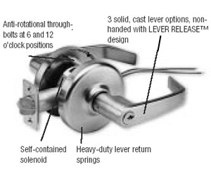 Designed to provide solenoid-operated
remote locking and unlocking, utilizing
the proven CL3300 Series Cylindrical
Lockset. Ideal for door control where
increased security is necessary. - Meets ANSI Grade 1 requirements.
- Self-contained integral solenoid allows
installation in standard cylindrical prep.
- Minimal power requirements – lock is
designed to lock or unlock as the
situation demands.
- Available in AC 12 or 24 volt systems.
(Locks are universal for AC or DC.)
- Mechanical cylinder override.
- Available as Fail Safe or Fail Secure.
- Cylinder options same as CL3300.
Available with Armstrong, Newport& Princeton lever designs
BHMA 605, 606, 611, 612, 613, 625, 626. Zinc
levers are plated to match BHMA finish.
250MA @ 12VAC/DC,
150MA @ 24VAC/DC
(Locks are universal for AC or DC.)
1-3/4" (44mm) - 2" (51mm).
Meets A156.2 Series 4000, Grade 1. Meets
A117.1 Accessibility Code of the ADA.
All locks listed for A label and lesser class
single doors, 4' x 10'.
| Electrified CL33900 Functions | CL33900 | Function Description | CL33903
Fail Safe | - Deadlocking latchbolt by lever either side, except when power on
locks outside lever.
- Power off/unlocks outside lever.
- Inside lever always free.
- Latchbolt retracted by key when locked electrically. | CL33905
Fail Secure | - Deadlocking latchbolt by lever either side, except when power off
locks outside lever.
- Power on/unlocks outside lever.
- Inside lever always free.
- Latchbolt retracted by key when power is off. |
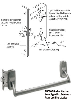 Designed to utilize the safety features of
the heavy-duty mortise crossbar exit device
and the added security of an electrically
controlled exit (ECE). - • Proven reliability and durability of the
Corbin Russwin Mortise Lockset.
• Available as Fail Safe or Fail Secure.
• Key always retracts latchbolt.
• Integral solenoid.
• Low voltage AC or DC systems available.
• Accepts wide range of trims.
Field reversible device; specify hand.
Mortise lock and strike not reversible.
Easily field cut to size. Standard 36"
(914mm) bar fits doors up to 36"
(914mm).
Standard: 1-3/4" (44mm).
2-3/4" (44mm).
Minimum width 5" (127mm).
5-3/4" (146mm); 4-1/2" (114mm)
depressed.
Brass, 3/4" (19mm) throw.
Brass.
8"(203mm) x 1-1/4"(32mm) heavy gauge
steel. Accommodates flat doors and
doors beveled 1/8" (3mm) in 2" (51mm).
Brass, bronze or stainless steel.
Heavy wrought, 7-1/2"(190mm) x 2-9/16"(65mm).
Standard: 13/16"(21mm) x
1-3/8"(35mm) oval seamless tubing.
Dogging standard.
Standard: machine screws.
Standard: ANSI strike.
Optional when specified.
12VAC 0.8 AMPS, 12VDC 0.8AMPS,
24VAC 0.4AMPS, 24VDC 0.4AMPS.
Meets A156.3, Grade 1.
All exit devices listed for safety as panic
hardware; devices comply with UL 305
standards for panic hardware.
All exit devices comply with NFPA 101
Life Safety Code.
BHMA 605, 606, 611, 612, 613, 622, 625,
626, 629, 630.
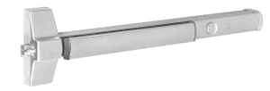
The delayed egress option provides
additional security and safety in a
strong line of exit hardware. The
delayed egress exit device is an
electromechanical device used to
secure interior or exterior openings. The option is available for rim, SecureBolt™,
surface vertical rod, concealed vertical rod and mortise devices in all standard
finishes.
The exit door is normally closed and latched. The Delayed Egress Exit Device “D” secures
the door in the locked mode with the solid Red LED indicating locked mode status.
Depressing the push pad for less than 3 seconds will sound the nuisance beep
without initiating the alarm. Depressing the exit bar for 3 seconds or longer
will initiate an irreversible local audible beeping tone and a visual amber
indicator until the device releases.
The person depressing the exit bar is denied egress for 15 or 30 seconds and
security personnel are alerted. After the delay time of 15 or 30 seconds the
device releases, the LED changes to Green, and the alarm changes to a steady
tone which continues to alarm until manually reset by key. The remote monitoring
contact outputs can be used to alert security personnel. Note: The 15-second time delay is standard. 30-second time delay is optional
(may be accepted by local jurisdiction).
- For use on hollow metal, wood or
composite interior or exterior doors.
- BOCA options available to comply
with National Building Code
requirements. BOCA option is not
suitable for installations in
accordance with NFPA 101.
- 1-3/4" door thickness standard; 2
and 2-1/4" optional.
- Standard 36" device fits 36"doors only.
Device cannot be cut less than 36".
- Option W048 fits doors 42"-48".
Devices cannot be cut less than 42".
- Available for ED4000 and ED5000
Series SecureBolt™, rim, mortise,
surface vertical rod and concealed
vertical rod exit devices.
Note: For surface vertical rod exit
devices, rod and latch guards
(provided by others) must be used.
- Key Switch Operation:
- Normal
- Bypass
- Reset/Delay
- Nuisance Delay
- Remote Control Inputs:
- Remote Reset
- Remote Bypass
- Bolt Position Monitor M91
- Outside Trim Monitor M93
- Mortise Electric Trim Control
SAF/SEC
- 30 Second Delay M88
- BOCA 15 Second Delay M89
- BOCA 30 Second Delay M90
- Power Supply: A regulated and
filtered power supply with a Fire
Alarm interface is required. 1 Amp
minimum @ 24VDC per device.
Special options will require more
amperage. Consult factory.
- Power Transfer: Allows the power
to make the transition from frame
to door without pinching or
removal of insulation.
- UL/cUL Listed
– Fire Exit Hardware
(GXHX/GXHX7)
– Controlled Exit Panic Device
(FUKD/FUKD7)
– Special Locking Arrangements
(FWAX/FWAX7)
- BHMA (ANSI 156.3 and ANSI
156.24) Directory of Certified Exit
Devices
- Input Voltage: 24VDC (+/- 10%)
Regulated and filtered.
- Standard Device: 500 mA
- Device with Electric Trim Control:
1.5 Amp
- Mortise Device with “Safe” or“Secure” option:
1.5 Amp
Utilizes a 1-1/8” mortise cylinder. Not
included unless specified.
Suffix “D” to device: ED5200D.
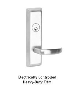
Electrically controlled trim provides
electric locking and unlocking of the
900 Series heavy-duty trim for the
ED5000 Series. The trim easily retrofits
into existing applications and is ideal
for stairwell towers, high security
areas, schools, hospitals and factories.
(Not available with mortise or
concealed vertical rod devices)
- ED5200(A) Rim
- ED5200S(A) SecureBolt™
- ED5400(A) Surface Vertical Rod
- ED5470(B) Surface Vertical Rod
- M98 – Security Monitor. A SPDT
switch that monitors the position
of the solenoid (lock and unlock
status).
- M99 – Trim gasket for exterior
applications.
Cylinder not included unless
specified. See ED5000 Series Exit
Device catalog for cylinder options.
- Utilizes the 900 Series heavy-duty
trim
- Available in Fail Safe or Fail Secure
operation
- 24VAC/VDC
- Internal rectifier accepts AC or DC
voltage
- Free Wheeling lever when locked
- Key override (specify cylinder)
- Plug connector with 4’ wire lead
(Exit device can be used as
the wire raceway)
- Solenoid: 330 mA @ 24 Volts
- Security Monitor Switch (M98):
4 AMP @ 250VAC
ED52005 N9903 626 RHR M98, 6P
Functions
Fail Safe
The x9903 trim is locked when power is on and unlocked when power is off. |
x9903
(Fail Safe) |
Function Description
• Lever is locked when power is on Free Wheeling)
• Power off allows entry from trim
• Inside device is always active for egress
• Mechanical key override (09 Function – Key allows lever to
retract latch bolt. Key can only be removed in
locked position.) |
| x = Trim design |
Fail Secure
The x9905 trim is locked when power is off and unlocked when power is on. |
x9905
(Fail Secure) |
Function Description
• Lever is locked when power is off (Free Wheeling)
• Power on allows lever activation for entry
• Inside device is always active for egress
• Mechanical key override (09 Function – Key allows lever to
retract latch bolt. Key can only be removed in
locked position.) |
| x = Trim design |
Monitors are used to indicate the unauthorized use of an opening or to signal
and control other opening hardware, such as magnetic locks. The monitoring
devices are equipped with one internal single-pole double-throw (SPDT) switch
per monitor.
Touchbar monitoring “M92” provides indication of the touch bar
being depressed. Also used as Request to Exit Switch(REX).
Outside Trim monitoring “M93” provides indication of the device
being operated from the outside.
Bolt Position monitoring “M91” provides indication on the position
of the latchbolt on rods.
SecureBolt™
Rim Exit Devices, Concealed Vertical Rod
Exit Devices, Surface Vertical Rod Exit
Devices, Mortise Exit Devices
UL listed for both Panic and Fire Exit Hardware.
5amps @ 28VDC SPDT contacts
Touchbar monitor specify “M92”
Outside Trim monitor specify “M93”
Bolt Position monitor specify “M91”
The 780 provides 2Amps of output current at 24VDC. The 780 can control a total
of 5 electric Dogging Devices. A separate switching device (key switch or
push button) must be used to control the locking device.
- 120VAC Input Power
- 24VDC @ 2Amp Output
- Fire Alarm Interface
The 781N controller is designed to control one or two electric latch pullback
devices. Operation can be set for sequential or individual control of doors.
When using a momentary normally open contact switch, the latch pullback delay
time feature can be adjusted from 1 to 20 seconds. An input to interface
with automatic door operator controllers is provided. Fire alarm input is
also provided.
Listed as an Exit Device Control Unit to UL 294 requirements.
- 120VAC 60HZ
- 9 Amp inrush for 100 milliseconds,
- Holding voltage 28 VDC @ .180 Amps
- Fire Alarm Interface

Power supplies are designed to provide
reliable filtered and regulated power for
long life to a variety of electrified
hardware components. All modular
power supplies are field-selectable for 12& 24 VDC and are designed to
meet UL
1481 Standards. Recommended for the
SAF, SEC, M97, delayed egress exit
devices and electric trim.
- Fire panel emergency release input
- PC Board mounted system LED
indicator
- Field-selectable 12 or 24 VDC output
- Regulated and filtered with input
and output protection
- Battery charging is provided from a
separate output terminal
- Inputs: 115VAC @600mA (230 VAC
optional), 50Hz/60hZ
- Outputs: 12/24 VDC @ 1 AMP, 1.5
AMP or 4 AMP, Filtered and
regulated output
- UL & cUL listed 1012 General
Purpose Power Supply
- D – Delayed Egress
- M97 – Electric Dogging
- SAF – Fail Safe mortise device trim
control
- SEC – Fail Secure mortise device
trim control
MPS10 and MPS15 power supplies are
available through Corbin Russwin. To
order, specify MPS10 or MPS15.
The ED4000 and ED5000 offer a complete range of electrical
options while maintaining a continuum in appearance, security and functions.
Ideal for use with monitoring security and alarm systems of most buildings.
Electric dogging feature provides
continuous latch retraction and touchbar
dogging simultaneously. When power is
applied to the exit device, depressing the
pushbar will continuously hold the
pushbar down and the latchbolt retracted
in the unlocked position. Removal or
interruption of power will release the
pushbar and the latch will extend.
SecureBolt™ Exit Device
Rim Exit Devices
Concealed Vertical Rod Exit Devices
Surface Vertical Rod Exit Devices
Mortise Exit Devices
UL listed for both Panic and Fire Exit
Hardware.
.35 Amps @ 24VDC-continuous duty
(2) 36-volt holding magnets holding force
(86Lbf. total).
Requires a power transfer by others.
Standard 24VDC power supply required.
Specify Quick Code M97.
Continuous-duty solenoid retracts the
bolt(s) for momentary or maintained
periods of time.
Latch Pullback provides a remote means of unlocking exit devices.
SecureBolt™ Exit Device
Rim Exit Devices
Concealed Vertical Rod Exit Devices
Surface Vertical Rod Exit Devices
Mortise Exit Devices
UL listed for both Panic and Fire Exit
Hardware.
Requires 781N Controller (120VAC
input, output sequencer for one or two
devices). Requires a 4-wire electrical
pivot or hinge by others.
Note: Using other power sources voids
warranty.
5.5 volt solenoid with 36 volt holding
magnet (.172 Amp).
9 Amp in rush @ 28VDC.
.180 Amps holding continuous duty.
Device bolts remain retracted for as long
as the device is energized. Removal of
power returns the device to the life safety,
self-latching mechanical mode.
Interface with central or local fire alarm
system, automatic door operators,
magnetic door locks, electric strikes, and
access control systems.
Specify Quick Code M94.
Mortise Device trim control provides a
remote means of locking or unlocking
Mortise Exit Device Trim. (ED5600 series
only)
This feature is provided by continuousduty
solenoids in the device mortise lock.
UL listed for both Panic and Fire Exit
Hardware.
24VDC 330 milliamperes
Fail-Safe units maintain the door locked
as long as the device is energized.
Fail-Secure units maintain the door
unlocked as long as the device is
energized. Standard 24VDC power supply required.
Specify Quick Codes “SAF” for Safe or “SEC” for Secure.

Ideal for high-use, high-abuse
situations on narrow and regular stile
doors in new construction and
renovations. - Meets ANSI Grade 1 requirements.
- Heavy-duty steel construction.
- Easy-to-use crossbar operation for
quick egress and ADA compliance.
- Low profile and projection for
barrier-free code compliance.
- No projecting parts to inhibit
egress.
- Throughbolted trims for strength
and security.
- Wide range of trim styles and finishes
to match other Corbin Russwin
products.
Alarm is activated when the exit device
touchbar is depressed. Factory preset for
standard alarm mode which automatically
resets after 5 minutes.
Alarm sounds continuously when the exit
device touchbar is depressed. Alarm must
be manually reset by keyswitch. (This
feature is selected by a switch on the
circuit board.)
Audible chirp.
“EMERGENCY EXIT-ALARM WILL
SOUND”
Factory preset for instant alarm.
Selectable feature for alarm to sound
when exit device touchbar is depressed
for more than 2 seconds. (This feature is
selected by a switch on the circuit board.)
Available in kit form for field retrofit.
Order ED40AK or ED50AK Kit.
10-second delay (after arming) permitting
egress (by turning key clockwise).
Ingress shunt alarm input for devices with
signal & outside trim monitors (M91 &
M93).
One 9 volt battery (included).
90 db @ 10 feet.
Requires one 1--1/8" (28mm) straight
cam mortise cylinder. Clockwise turn
arms the alarm, counter-clockwise turn
disarms or silences the alarm. Low
audible chirp indicates alarm has been
activated. (Cylinder not included unless
specified.)
A red LED indicator will illuminate every
30 seconds when the alarm is armed.
Built-in safety monitor sounds alarm
when tampering occurs.
M61
ED4000 Series x M61
ED5000 Series x M61
See catalog for cylinder
options.
ED40AK
ED50AK
See catalog for door
width and cylinder options.
*Cannot retrofit to existing
SVR devices.
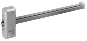 Ideal for retail, restaurants,
warehouses, and other applications
that require a fire exit with an
emergency alarm. - Meets ANSI Grade 1 requirements.
- Fully contained alarm; no wiring is
needed
- Tamper-resistant design
- Non-handed
Alarm is activated when the exit device
touchbar is depressed. Contains solid
state circuitry with adjustable sensitivity.
Emits audible alarm, signaling emergency
or unauthorized use of door.
Permits controlled authorized egress by
using key. Alarm will not sound if door is
closed within 20 seconds.
“EMERGENCY EXIT-ALARM WILL
SOUND”
One 9 volt alkaline battery (not
included).
85db @ 10 feet.
Requires one rim cylinder (not included
unless specified).
LED indicates power on, alarm on, delay
feature on.
Available in kit form for field retrofit.
Specify ED82AK x finish.
ED8200 Panic Rated Rim Exit Devices
ED8200B 1-1/2 hour Fire Rated Rim Exit
Devices
ED8200 x M61 x finish (device with
alarm)
ED82AK x finish (retrofit kit)
ED8200 x M61 x M62 x finish
ED82AK x M62 x finish
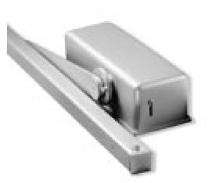 Closer holder devices are used on fire
doors that need to be held open but must
close in case of fire. The DC26900 device
utilizes theThe DC2600 closer with an
affixed electromagnet to release the door
during an alarm. Free swing arm option
also available. A wise choice for patient
room applications. | Voltage | AMP Draw | | 24 VAC | .083 | | 24 VDC | .150 | | 12 VAC | .077 | | 12 VDC | .266 | | 120 VAC | .042 | | 120 VDC | .044 |
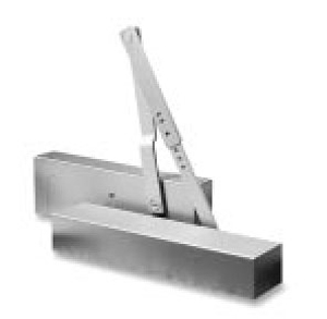 Closer holder devices are used on fire
doors that need to be held open but must
close in case of fire. The DC469000 device
uses an aluminum closer body and offers
detectored and non-detectored models.
Perfect for cross-corridor installations. Voltage | Master Unit
AMP Draw | Companion
AMP Draw |
24 VDC | 30 mA | 80 mA | 24 VAC | 47 mA | 80 mA | 120 VAC | 33 mA | 17 mA |
| 


