
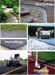
 CONCRETE PAVER AND ASPHALT PAVEMENT RESTRAINTS
StructurEdge, AsphaltEdge and AthletEdge
Complete 3-Part Specifications are listed below the product descriptions.
(Please scroll down the page to view) STRUCTUREDGE™
StructurEdge is a flexible L-shaped aluminum paving restraint designed as an
edge restraint for pavers. It provides a clean, unobstructed edge along the
paver installation allowing the use of a power edger directly adjacent to the
paving stones. It’s quick and easy to install and readily forms to curves,
angles and straight runs. StructurEdge is a permanent paving restraint system
that is designed to be easier to install and out-perform plastic, PVC and steel
systems. Our interlocking sliding connectors eliminate weak points. The tight-fitting
L-shaped design promotes healthy grass and accommodates the tight placement
of irrigation heads (unlike bulky plastic triangular restraints). StructurEdge
readily forms to curves, radii and angles, allowing wide installation flexibility.
Available in 3/32, 1/8, and 3/16 inch thicknesses by 1 5/8 or 2 ¼ inch
heights. Finishes available are Mill (Natural) and Black. ASPHALTEDGE™
AsphaltEdge is the only patented product specifically designed to perform as
an integral edge restraint system for asphalt. AsphaltEdge provides full and
consistent material thickness to the edge of the pavement. It is designed to
help prevent broken edges and provide a finished, maintainable, long-term solution
for asphalt installations. Perfect for straight and curved runs. AsphaltEdge
is engineered to extend the life of asphalt pavement by helping to prevent broken
edges and provide a finished, maintainable look along the asphalt border. Specifically
designed for asphalt over aggregate, asphalt overlay, and asphalt over concrete,
including residential, commercial and industrial applications. Product is available
in 1, 1 ½, 2, 2 ½, 3 and 4 inch depths. Finishes available are
Mill (Natural) and Black. ATHLETEDGE™
AthletEdge is a line of flexible, L-shaped aluminum athletic surface/asphalt
restraints designed for use over aggregate, asphalt and concrete. From running
tracks to tennis courts, AthletEdge provides a clean appearance on your sports
installations. AthletEdge provides the same high quality characteristics as
AsphaltEdge with the added benefit of sidewall “weep holes” to aid
lateral drainage. Product is available in 1, 1 ½, 2, 2 ½, 3 and
4 inch depths. Finishes available are Mill (Natural) and Black. StructurEdge: SHORT SPECIFICATION Place the following in specification section that will be used for the main
paver work (for example, Section 02780 Paver, or etc.). The architect to edit
size, thickness, length, and finish required for the project. Comments shown
in “italics.” PART 1 GENERAL 1.01 WARRANTY
Actual article number will be determined by location within the Part 1 portion
of specification. A. 15-year limited material warranty for paver restraint edging from manufacturing
defects in workmanship or material. PART 2 PRODUCTS 2.01 PAVER RESTRAINT EDGING
Actual article number will be determined by location within the Part 2 portion
of specification. A. Product: PermaLoc StructurEdge, 3/32 inch (2.4 mm) x 1-5/8 inches (41 mm)
high, 1/8 inch (3.2 mm) x 1-5/8" (41 mm) [2-1/4" (57 mm)] high, 3/16
inch (4.8 mm) x 1-5/8" (41 mm) [2-1/4" (57 mm)] high, extruded aluminum,
6063 alloy, T6 hardness, paver restraint edging for straight-line and curvilinear
applications in corrugated L-shaped profile, as manufactured by PermaLoc Corporation,
Holland MI 49424, telephone (800) 356-9660 or (616) 399-9600. Horizontal base
shall have holes spaced 4 inches (102 mm) apart along its length to receive
spikes.
B. Thickness: 3/32 inch (2.4 mm) gage section shall have 0.170 inch (4.32 mm)
thick exposed top lip, 1/8 inch (3.2 mm) gage section shall have 0.190 inch
(4.83 mm) thick exposed top lip, and 3/16 inch (4.8 mm) gage section shall have
0.210 inch (5.33 mm) thick exposed top lip.
C. Length: 8 feet (2.44 meters).
D. Connection Method: Section ends shall splice together with horizontal 0.060
inch (1.52 mm) thick x 1 inch (25 mm) wide x 4 inches (102 mm) long aluminum
sliding connector.
E. Spikes: 3/8 inch x 10 inches (9.5 mm x 254 mm) bright spiral steel spike.
Use plastic washers if desired.
F. Finish: Natural Mill Aluminum and Black DuraFlex Painted, AAMA 2603, electrostatically
baked on paint. PART 3 EXECUTION
Editorial Comment (shown in italic): The following information for base preparation
and installation shall be specified in specification section for Paver and is
recommended only as a generally accepted paver installation method. Professional
assistance should be sought with respect to the specification and construction
of a specific project: Preparation of Base for Pavers: Remove excess soils and unstable subbase materials.
Compact subgrade to 95% proctor density test. Paver Base Installation: Backfill excavated area with appropriate depth aggregate
material as specified in Unit Paver Section. Base shall be compacted in 2 to
3 lifts to achieve proper density. The base needs to extend 6 inches (152 mm)
to 12 inches (305 mm) beyond the edge of paver installation. Screed sand (or
equivalent material as specified) over base to uniform thickness of not less
than 1 inch (25 mm) and not more than 1-1/4 inches (32 mm). After installation of restraint edging and pavers: Sweep fine sand (or equivalent
material as specified) into joints. Make several passes with a plate compactor
with no less than 3,000 - 5,000 lbs. (1,361 kg - 2,268 kg) centrifugal compaction
force and operates at 80 to 90 hertz. Continue sweeping sand into joints. Make
several passes alternating direction of compactor each time. Remove excess sand
from paver installation. 3.01 INSTALLATION OF PAVER RESTRAINT EDGING
Actual article number will be determined by location within the Part 3 portion
of specification. A. Preparation: Ensure that all underground utility lines are located and will
not interfere with the proposed edging installation before beginning work.
B. Locate border line of edging with string or other means to assure border
straightness and curves as designed.
C. Edging Installation: Install base of edging resting on compacted level base
and facing [away from] [towards and under] paver, drive 3/8" x 10"
(9.5 mm x 242 mm) bright spiral steel spikes through edging holes in section
base of paver restraint edging at spaces for following applications:
1. Anchor each section end with spike.
2. Patios and Walkways: 12 inches (305 mm) to 24 inches (610 mm) on center.
3. Driveways: 4 inches (102 mm) to 12 inches (305 mm) on center.
4. Heavy Vehicular Loads: 4 inches (102 mm) on center.
D. Securely connect sections together in accordance with manufacturer’s
instructions.
E. Install pavers.
May 1, 2003
AsphaltEdge: SHORT SPECIFICATION Place the following in specification section that will be used for the main
paver work (for example, Section 02740 Bituminous Concrete Pavement, or etc.).
The architect to edit size, thickness, length, and finish required for the project.
Comments shown in “italics”. PART 4 GENERAL 4.01 WARRANTY
Actual article number will be determined by location within the Part 1 portion
of specification. A. 15-year limited material warranty for asphalt restraint edging from manufacturing
defects in workmanship or material. PART 5 PRODUCTS 5.01 ASPHALT RESTRAINT EDGING
Actual article number will be determined by location within the Part 2 portion
of specification. A. Product: PermaLoc AsphaltEdge, with 0.210 inch (5.33 mm) thick exposed top
lip x 1" (25 mm) [1-1/2" (38 mm)] [2" (51 mm)] [2-1/2" (64
mm)] [3" (76 mm)] [4" (102 mm)] high x 8 feet (2.44 meters) long,
extruded aluminum, alloy 6005, T-5 hardness as manufactured by PermaLoc Corporation,
Holland MI 49424, telephone (800) 356-9660 or (616) 399-9600. Horizontal base
to have upward facing angle profile designed to integrate restraint and asphalt
surfaces for straight-line and curvilinear applications. Section shall have
holes in base spaced 4 inches (102 mm) apart along its length to receive anchors.
B. Connection Method: Section ends shall splice together with horizontal 0.060
inch (1.52 mm) thick x 1 inch (25 mm) wide, or 0.530 inch (13.5 mm) wide for
1 inch (25 mm) high edging x 4 inches (102 mm) long aluminum sliding connector.
C. Anchors: 3/8 inch x 10 inches (9.5 mm x 254 mm) bright spiral steel spike,
3/16 inch x 1-1/2 inches (4.8 mm x 38 mm) or longer Ardox concrete nail, or
drive pin fastener equal to Hilti DX 40 powder actuated pin or Ramset Trakfast
Automatic Fastening System pin.
D. Finish: Natural Mill Aluminum and Black DuraFlex Painted, AAMA 2603, electrostatically
baked on paint. PART 6 EXECUTION
Editorial Comment (shown in italic): The following information for base preparation
and installation shall be specified in specification section for Asphalt Pavement
and is recommended only as a generally accepted pavement installation method.
Professional assistance should be sought with respect to the specification and
construction of a specific project: Preparation of Base for Asphalt Pavement: Remove excess soils and unstable
subbase materials. Compact subgrade to 95% proctor density test. Asphalt Pavement Base Installation: A road gravel as recommended by project
engineer meeting ASTM standards for road construction is ideal. Larger aggregate
will make secure anchoring more difficult, causing undue twisting, leaning,
or movement. Asphalt Pavement Installation: Shall be specified as recommended by project
architect or engineer. 6.01 INSTALLATION OF ASPHALT RESTRAINT EDGING
Actual article number will be determined by location within the Part 3 portion
of specification. A. Base Installation:
1. Extend base at least 6 inches (152 mm) beyond edge of restraint edging.
2. Level base beneath restraint edging.
B. Edging Installation:
1. Install edging leaving 3/8" (9.5 mm) between sections for expansion.
2. Drive spikes through edging holes in base of asphalt restraint edging (or
drive nails through aluminum base when using powder actuated fastening system)
at spaces for following applications: [Editorial note: Spacing depends on age,
hardness, depth, and type of base material (aggregate, asphalt, or concrete),
radius being formed, anchoring spacing, and lengths of anchors.]
a. Anchor each section end with anchor.
b. Aggregate Base: Spiral steel spikes at 4 inches (102 mm) to 12 inches (305
mm) on center.
c. Softer or Thinner Asphalt Base: 3/8 inch x 10 inches (9.5 mm x 254 mm) spiral
steel spikes at 4 inches (102 mm) to 12 inches (305 mm) on center spacing.
d. Older, Harder, or Thicker Asphalt Base: Hilti DX A41 Fully Automatic Powder
Actuated Tool is desirable where sufficient hold can be obtained. Provide 1-1/2
inches (38 mm) to 2-1/2 inches (64 mm) nail at 4 inches (102 mm) to 12 inches
(305 mm) on center spacing with applicable charge recommended.
e. Concrete Base: Hilti DX A41 Fully Automatic Powder Actuated Tool is desirable
where sufficient hold can be obtained. Provide 3/4 inches (19 mm) to 1 inches
(25 mm) nail at 4 inches (102 mm) to 12 inches (305 mm) on center spacing with
applicable charge recommended. Anchor into outer 1 inch (25 mm) of base of restraint
edging and not less than 2 inches (51 mm) from edge of concrete.
3. Securely connect sections in accordance with manufacturer’s instructions.
Provide additional anchors at closer spacing as necessary to firmly secure edging
for permanent intended use.
C. Pavement Installation:
1. If asphalt installation is over restraint edging, avoid excessive asphalt
temperatures to minimize aluminum expansion.
2. Lay asphalt pavement adjacent to and approximately ½ inch (12.7 mm)
over top of restraint edging, depending on expected compaction results. Then,
compact first pass with desired equipment within 6 inches (152 mm) of restraint
edging. “Pinch roll” to create a hard joint. Subsequent passes may
be directly against or over top of edging to ensure complete compaction of asphalt
pavement.
3. Finish pavement shall be compacted and level with, but not to exceed 1/4
inch (6.4 mm) above top of restraint edging.
D. Backfill side of edging on turf side and compact backfill material along
edging to provide top of edging at ½ inch (13 mm) above finish grade
on turf side. May 1, 2003 AthletEdge: SHORT SPECIFICATION Place the following in specification section that will be used for the main
paver work (for example, Section 02740 Athletic Pavement, or etc.). The architect
to edit size, thickness, length, and finish required for the project. Comments
shown in “italics.” PART 1 GENERAL 1.01 WARRANTY
Actual article number will be determined by location within the Part 1 portion
of specification. Note: manufacturer has a more detailed warranty for AthletEdge...
check with manufacturer for application of 15 year warranty. A. 15-year limited material warranty for athletic court/track restraint edging
from manufacturing defects in workmanship or material. PART 2 PRODUCTS 2.01 ATHLETIC COURT/TRACK RESTRAINT EDGING
Actual article number will be determined by location within the Part 2 portion
of specification.
A. Product: PermaLoc AthletEdge, with 0.210 inch thick (5.33 mm) exposed top
lip x 1-1/2" (38 mm) [2" (51 mm)] [2-1/2" (64 mm)] [3" (76
mm)] [4" (102 mm)] high x 8 feet (2.44 meters) long, extruded aluminum,
alloy 6005, T-5 hardness as manufactured by PermaLoc Corporation, Holland MI
49424, telephone (800) 356-9660. Horizontal base to have upward facing angle
profile designed to integrate restraint and athletic court/track rubberized
asphalt surfaces for straight-line and curvilinear applications. Section shall
have holes in base spaced 4 inches (102 mm) apart along its length to receive
anchors. Sidewall to have weep holes spaced approximately 2 feet (610 mm) on
center for drainage from athletic surface.
B. Connection Method: Section ends shall splice together with horizontal 0.060
inch (1.52 mm) thick x 1 inch (25 mm) wide x 4 inches (102 mm) long aluminum
sliding connector.
C. Anchors: 3/8 inch x 10 inches (9.5 mm x 254 mm) bright spiral steel spike,
3/16 inch x 1-1/2 inches (4.8 mm x 38 mm) or longer Ardox concrete nail, or
drive pin fastener equal to Hilti DX 40 powder actuated pin or Ramset Trakfast
Automatic Fastening System pin.
D. Finish: Natural Mill Aluminum and Black DuraFlex Painted, AAMA 2603, electrostatically
baked on paint.
PART 3 EXECUTION
Editorial Comment (shown in italic): The following information for base preparation
and installation shall be specified in specification section for Athletic Pavement
and is recommended only as a generally accepted pavement installation method.
Professional assistance should be sought with respect to the specification and
construction of a specific project:
Preparation of Base for Athletic Pavement: Remove excess soils and unstable
subbase materials. Compact subgrade to 95% proctor density test.
Athletic Pavement Base Installation: A road gravel as recommended by project
engineer meeting ASTM standards for road construction is ideal. Larger aggregate
will make secure anchoring more difficult, causing undue twisting, leaning,
or movement.
Rubberized Athletic Pavement Installation: Shall be specified as recommended
by project architect or engineer.
3.01 INSTALLATION OF ATHLETIC COURT/TRACK RESTRAINT EDGING
Actual article number will be determined by location within the Part 3 portion
of specification.
A. Base Installation:
1. Extend base at least 6 inches (152 mm) beyond edge of restraint edging.
2. Level base beneath restraint edging.
3. If asphalt installation is over restraint edging, avoid excessive asphalt
temperatures to minimize aluminum expansion.
B. Edging Installation:
1. Install edging leaving 3/8" (9.5 mm) between sections for expansion.
2. Drive spikes through edging holes in base of athletic restraint edging (or
drive nails through aluminum base when using powder actuated fastening system)
at spaces for following applications: [Editorial note: Spacing depends on age,
hardness, depth, and type of base material (aggregate, asphalt, or concrete),
radius being formed, anchoring spacing, and lengths of anchors.]
a. Anchor each section end with anchor.
b. Aggregate Base: Spiral steel spikes at 4 inches (102 mm) to 12 inches (305
mm) on center.
c. Softer or Thinner Asphalt Base: 3/8 inch x 10 inches (9.5 mm x 254 mm) spiral
steel spikes at 4 inches (102 mm) to 12 inches (305 mm) on center spacing.
d. Older, Harder, or Thicker Asphalt Base: Hilti DX A41 Fully Automatic Powder
Actuated Tool is desirable where sufficient hold can be obtained. Provide 1-1/2
inches (38 mm) to 2-1/2 inches (64 mm) nail at 4 inches (102 mm) to 12 inches
(305 mm) on center spacing with applicable charge recommended.
e. Concrete Base: Hilti DX A41 Fully Automatic Powder Actuated Tool is desirable
where sufficient hold can be obtained. Provide 3/4 inches (19 mm) to 1 inches
(25 mm) nail at 4 inches (102 mm) to 12 inches (305 mm) on center spacing with
applicable charge recommended. Anchor into outer 1 inch (25 mm) of base of restraint
edging and not less than 2 inches (51 mm) from edge of concrete.
3. Securely connect sections in accordance with manufacturer’s instructions.
Provide additional anchors at closer spacing as necessary to firmly secure edging
for permanent intended use.
C. Athletic Surface and Backfill Installation: Lay finished athletic surface
approximately 1/8 inch (3.2 mm) higher than top of restraint edging. Backfill
side of edging on turf side and compact backfill material along edging to provide
top of edging at 1/2 inch (13 mm) above finish grade on turf side.
May 1, 2003
Permaloc Corporation
13505 Barry Street
Holland MI, 49424
Tel: (616) 399-9600
Toll Free: 1-800-356-9660
Fax: (616) 399-9770
E-mail: info@permaloc.com
Web site: http://www.permaloc.com
|