
Today practically every door in modern commercial, industrial, and institutional
buildings is opened by the person passing through and closed by a mechanical door
closer which should keep the door under orderly control at all times. The power
to close the door is generated by the springs inside the closer. The speed of
the doors closing swing is controlled by regulated hydraulic circuits. Ideal door
"conduct" is illustrated in the diagram in the adjacent photo and described
below. It can be achieved by equipping each door with the appropriate LCN door
closer.
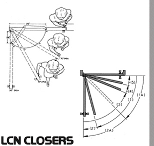
The diagram shows the main parts or stages in correct door operation, whether
under manual or mechanical control or a combination of the two. The numbers refer
to the door positions shown on the diagram.
- On the opening swing, the door closer’s job is to let the door open
easily, except at the end of the swing where backcheck is desired.
- Backcheck is a feature that cushions the opening swing to prevent the door
from slamming into the stop. A few special closers designed for potentially abusive
applications begin the backcheck function much earlier (1A & 2A).
- Through the long closing arc, a uniform, reasonable (main) speed should be
maintained.
- A gradual transition prevents an abrupt change from main speed control to
the final latching arc.
- The latching arc allows the door to close quietly and firmly.
As a controlled door is opened, the spring of the closer is compressed which builds
up the power to close the door. Normally, more opening force would be required
as spring compression increases. However, an LCN closer changes its arm position
as the door opens, increasing the door’s leverage. This offsets the spring
compression, resulting in greater ease in opening the door.
This is shown in the in the adjacent photo, in which a person is opening a door
equipped with an LCN overhead concealed closer. In this closer the track roller
(A) applies the closer power to the door. Note that when the door is in the closed
position the roller is 23" (584 mm) from the hinge edge. When the door has
opened to 30º the roller is only 19-3/4" (502 mm) from the hinge edge.
At 60º the distance is down to 13-3/4" (349 mm) and at 90º it is
only 8-1/4" (210 mm). The changing arm geometry gives increasing leverage
over the door, enabling the person passing through it to easily overcome the growing
power of the spring.
When the person releases the door and the closer takes over, spring power is applied
through the arm system to close the door. Because the spring has been compressed,
its power is very high. As the door closes the spring expands, gradually losing
its power. The roller moves farther out on the door to give the closer increased
leverage to compensate for lost power. When the door finally must be closed against
the latch, the leverage is greatest. LCN control is a compensating force, always
tending to help the people who use the door.
The 1990 Americans with Disabilities Act (ADA) and barrier free accessibility
codes specify that many non-fire-rated doors must meet reduced opening force requirements.
LCN has developed both manual and powered products to meet these requirements.
HOW TO SELECT A DOOR CLOSER
For the LCN Closer Selection Guide, see the TABLE portion of this Profile.
Door closers are available in two styles - concealed or surface mounted. In choosing
a closer style for a particular application, consideration should be given to
the type of door being controlled, frame conditions, aesthetic requirements, and
control features needed. Information contained in the following material can serve
as a guide in selecting the style and model of closer to meet specific requirements.
Closers concealed in the head frame over the door are out of sight and entirely
out of the pedestrian’s way. They cannot be harmed by scrub water, cleaning
chemicals or floor dirt, and are protected from airborne contaminants, like dust.
They are easy to reach for regulation without removing any parts. Closers for
frame sections as thin as 1-3/4" (44 mm) are available.
Closers located within the door itself are also hidden and protected. On interior
doors of common sizes they do an excellent job, yet they cost little more than
surface applied closers.
Closer location is subject to the considerations of practicality and appearance.
Good taste usually decrees that closers on doors along a corridor be located on
the room side of the door so they are out of the line of sight from the corridor.
Closers should be placed on the inside of exterior doors for appearance and to
shelter them from the elements.
Heavy duty closers should always be used in these places:
- Schools or public buildings where hard usage is expected.
- Exterior doors.
- Doors subject to draft, winds, or air pressure differentials.
- High frequency doors such as those on department stores, malls, or mixed use
tenancies.
Double lever arm closers can provide control under difficult conditions for either
interior or exterior doors. A parallel arm system is a type of double lever arm
where the main arm is parallel to the face of the closed door. Functions available
in double lever arm systems are: REGULAR, HOLD-OPEN, FUSIBLE LINK, EXTRA DUTY
(EDA) and CUSH-N-STOP (CUSH).
Single lever arm (track) closers may be used on interior or sheltered exterior
doors. The hold-open function in a single lever arm system is provided by either
the track or, in the case of life safety closer/holders, the cylinder assembly.
Available single lever arms are: STANDARD, DOUBLE EGRESS, and SWING-FREE.
The 1990 Americans with Disabilities Act (ADA) and ANSI Standard A117.1 describe
maximum opening force limitations for certain non-fire-rated doors. The last page
of each closer section in each Snapshot of this electronic program includes a
section titled REDUCED OPENING FORCE CLOSERS. This section lists closers in that
specific series that will comply with a maximum opening force based on the width
of the door.
Any manual door closer, including those certified by BHMA to conform to ANSI
Standard A156.4, that is selected, installed, and adjusted based on ADA or other
reduced opening force requirements may not provide sufficient power to reliably
close and latch a door.
See the “Power Operators” Profile for information on Auto-Equalizer™
and Equalizer® systems that meet reduced opening force requirements without
affecting closing power.
Corner brackets were once the only satisfactory way to install a closer on the
push side of a door. They still meet special requirements, which other mountings
do not satisfy.
A plate is now commonly used to drop (lower) closers to meet special conditions
or adapt a closer to door or frame surfaces that are not adequate for normal mounting
patterns.
Specialized brackets, adapters, and parallel arm shoes are available to simplify
the installation of closers with a variety of frame and door conditions. The most
commonly used are listed with each closer. Consult LCN for assistance if you are
not sure.
All LCN closers are shipped with a wood and machine screw pack unless other fasteners
are ordered. This standard screw pack is suitable for wood or properly reinforced
hollow metal frames and metal or solid core wood doors. For selected closers,
metric machine screws are available in lieu of UNC/UNF machine screws. Use of
a power tool to install fasteners is not recommended.
When attaching closers to hollow core doors, optional THROUGH BOLTS (TB) are
recommended to minimize crushing or squeezing the door. Through bolting can also
provide a very strong mechanical connection for potentially abusive applications.
TB’s feature a knurled and rounded head to grip the door firmly and resist
tampering. Because the TB barrel extends completely through the door, when ordering
the door thickness must be specified if it is other than 1-3/4" (44 mm).
TB’s are only available for 1/4-20 machine screws.
For high security applications, TORX machine screws are available with most
closers. These are standard for all exposed fasteners with HIGH SECURITY CLOSERS.
TORX fasteners feature a hex lobular drive with a security pin in the center.
They can only be installed or removed with a special set of bits available from
LCN.
See “LCN Closers and Power Operators” for information about the available
finishes.
(See adjacent drawings)
Many LCN closers can be ordered with a delayed action function built into the
cylinder. Delayed action is a special hydraulic circuit that provides additional
time to pass through the door. A special regulating screw controls the closing
speed from maximum opening through approximately 75º. After that point the
normal main speed resumes control to close the door. Delayed action is not available
with single lever arm (track) closers.
Advanced Variable Backcheck (AVB) is available with high security and 4110
series closers to begin cushioning the opening swing at about 45º (2A) instead
of the usual 75º (2). AVB is especially suited for potentially abusive applications.
Multi-point (ME series) closer/holders can be ordered with a hold-open bypass
function. This feature does not allow hold-open to take effect within a selected
range of door swing.
Temperature changes can affect the operation of common door closers by changing
the viscosity of the hydraulic fluid inside the closer. As temperature rises,
the fluid thins out closing the door more rapidly. As temperatures decrease, the
fluid thickens causing the closer to close the door very slowly.
LCN uses all weather fluid to minimize the need for seasonal readjustment of
the closing speed under normal temperature ranges. All LCN heavy duty, architectural
grade closers feature a special hydraulic fluid, Liquid X. More costly than other
fluids, it’s constant viscosity permits an operating range of +120ºF
(49ºC) to -30ºF (-35ºC) that eliminates the need for seasonal adjustments.
While butt hinges provide the most common method of hanging doors, some doors
are hung on pivots centered in the door, others on offset pivots. Surface mounted
closers will handle doors hung in any of these three ways. LCN 4020 Series closers
can even control a "balanced" door installation. Concealed closers may
conflict in location with pivot leaves and thus may require special templating.
Three basic rules apply to maximum degree of opening.
- It is best to let the door swing as far as it can swing freely. Some closers
are mounted in different locations for different degrees of opening.
- Use a mechanical stop when a door cannot swing 180º or at the selected
hold-open point of a double lever arm system. The mechanical stop can be mounted
on the floor, wall, overhead, or built into the closer (CUSH-N-STOP) arm.
- The closer should be positioned so backcheck takes place well in advance of
the stop position to cushion the opening swing and prevent door and frame damage
from an abrupt stop.
The width of the door is the main consideration in determining the correct closer
size. Size here refers to the minimum spring power and hence, the closing force
generated by the closer.
In the LCN General Closers Catalog, the interior and exterior TABLE OF SIZES
for each closer are set up for ranges of door width and assume normal operating
conditions. If a door is of exceptional height, weight, special construction,
or if drafts and air pressure differentials exist, increased closer power should
be considered. Call LCN for assistance with special design situations.
Door thickness may be a factor. A concealed-in-the-door closer should not be
used in a hollow metal door less than 1-1/2" (38 mm) thick or a wood door
under 1-3/4" (44 mm). Exceptionally thick doors can affect hinge and pivot
centers to the extent that closer functions and geometry are also affected.
The depth of the door’s top rail is important to nearly every closer
installation. Narrow top rails may require plates to successfully mount the closer.
An insufficient top rail in flush, hollow, or composition filled doors may make
concealed-in-the-door installations impractical.
Some door closers are handed. When approaching a door from the push side, if hinged
on the left, it is a left hand door; if hinged on the right, it is a right hand
door.
For purposes of handing door closers, right hand reverse bevel and left hand
are identical. Also, left hand reverse bevel and right hand are identical.
The hand of the closer is the same as the hand of the door for all except corner
bracket installations that require a closer handed opposite the hand of the door.
Occasionally the physical limitations of the selected closer may not provide the
desired functions or degree of opening. Standard templated locations may interfere
with other applied hardware. In these situations, contact the LCN Applications
Engineering Department for assistance. Customized installation templates or products
may be available to solve an unusual application.
Please visit our website at www.lcnclosers.com for an illustrated “LCN Glossary”
that defines all key components and concepts needed to understand door closer
operation. This is of great value to specifiers and designers at every level of
experience and knowledge.
LCN – Ingersoll Rand Security Technologies
121 West Railroad Avenue
P.O. Box 100
Princeton IL 61356
Tel: (800) 526-2400
Fax: (800) 248-1460
E-mail: trade_marketing@irco.com
Web site: http://www.lcnclosers.com
|