![]()
Ideal Manufacturing,
Inc.
2011 Harnish Blvd.
Billings, MT 59101
Tel: (406) 656-4360
Toll-Free: (800) 523-3888
Fax: (406) 656-4363
E-mail: ideal/ltd@wtp.net
Web site: http://www.tilt-a-way.com
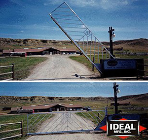
Tilt-A-Way™
Vertical Lift Gates
Engineered to exceed demanding security requirements, Tilt-A-Way™ Vertical Pivot Gates are recognized for setting the standards in design quality and performance. For either low or high security applications, Tilt-A-Way gates are manufactured and tested to withstand the harshest operating conditions and complement any security access system.
Tilt-A-Way Vertical Pivot gates are twist and sway resistant. Barriers are manufactured in either aluminum or steel. Patented horizontal sway brace design and manufacturing techniques combined with patented in-line balance systems out perform any other gate available and last up to 40 times longer. The 50" low profile hydraulic operator accommodates custom barrier designs. If a power failure occurs, Tilt-A-Way barriers can be raised or lowered manually with only 12 to 15 pounds lift. And, a standard safety control switch stops the barrier regardless of its position should the balance system malfunction.
Barrier Construction
The barrier is constructed to resist
twist or sway. Tilt-A-Way gates resist high winds. We will custom build
a barrier to your design.
ALUMINUM
- Barrier material – 4" Sch 40 round
tube
- Square sway bars – 1-1/4" x 1-1/4"
x 1/8" square tube
- Uprights – 2" x 2" x 3/16" square
tube
- Screen – Amplimesh aluminum
STEEL
- Barrier material – 4" Sch 20 round
tube
- Square sway bars – 1-1/4" x 1-1/4"
x .087 square tube
- Uprights – 2" x 2" x .120 square
tube
- Screen – #9 Galvanized steel
Satisfaction is guaranteed. If not satisfied within 6 months, return the physically undamaged barrier and pedestal; we will refund the purchase price. 3 year limited warranty on workmanship and materials except for electrical components. Design subject to change without notice.
OPTIONS
There are many options to meet your
application. Design your own gate or choose from one of our many designs.
• Photo Eyes
• Card Readers
• Proximity Card Readers
• Keyless Entries
• Key pads
• Loop Detectors
• Reversing edge
• Gate status lights
• Magnetic locks
• S. O. S. - siren operator sensors
• Cold weather package
• Weather guard package
• Remote control
• Infrared
• C.C.T.V.
• Master slave (to swing 2 gates together)
• Contact Ideal Manufacturing, Inc. for additional options.
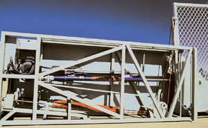
Hydraulic Model KJB-25
The hydraulic system has a low profile pedestal. A well organized system. Long stroke hydraulic cylinder with a control rod along side the cylinder rod. Springs are pulled in a straight line for long life. Compact hydraulic unit in upper left hand corner of photograph. The cylinder is adjustable for gate height on the far end of the barrier.
The hydraulic cylinder and control rod are mounted on a heavy support. Cables are connected to the springs with a special built adapter. Cables travel over a sheave and are adjustable for any weight change. Using this cable system extends the spring life by 40 times over the old fashioned and ineffective way of bending the springs over a fulcrum.
- We can swing a gate up to 9' tall
and 25' long.
- With 2 operators, a 50' roadway
can be accessed.
- Patented balance system. (2) springs
pulled in a straight line.
- Balance system has built-in safety
controls.
- L.E.D. circuit board with timer
to close.
- Hydraulically operated for smooth
operation, with slowdowns on both ends of travel for smoother operation.
- Only 7 moving parts for a low
maintenance installation.
- Cross brake 16 gauge steel panels.
- Patented sway braces on barrier
to resist twisting or swaying.
Electrical Requirements
120 Volt 11.2 Amps is standard.
Options:
1. 208-230 Volt single phase - 5.6
Amps
2. 208-230 Volt three phase - 3.2
Amps
3. 460 Volt three phase - 1.6 Amps
Pedestal
1. Welded pedestal frame 2" x 2"
x .120 steel tubing.
2. Front support on frame is 2"
x 4" x .120 steel tubing.
3. Covered with 16 gauge steel.
4. All panes cross-broke.
5. Stainless steel hinges.
Operator
1. 1 h.p. 110/220 volts.
2. 4 gallons per minute, 1000# pressure.
3. 1-1/2 gallon reservoir.
4. By-pass valves for hand operation.
Balance System
1. All balance springs pulled in
a straight line.
2. 3/8" cable to connect springs
to barrier.
3. Cast iron sheaves with needle
bearing at transfer point between spring and barrier.
4. Sheaves adjustable to compensate
load.
5. 1" Acme threaded bolt. One each
for spring to bring the spring to the right tension.
6. Brass nut on all 1" Acme threaded
bolt.
7. Insert in each end of spring
to accommodate hook to attach to cable and other end to 1" Acme adjusting
bolt.
8. 1-7/16" shaft with pillow block
bearings on barrier pivot.
Gate Opener
1. 38" cylinder stroke.
2. Cushioned stop, both ends.
3. Limit switches, both ends of
travel.
4. Adjustable stop for barrier at
closed position.
Safety
- Shut off power if balance systems
should fail.
Security
- Barrier locks in down position.
- All inspections doors to accept
padlock.
15 REASONS TILT-A-WAY IS SUPERIOR!
1. The barrier is made of steel or aluminum for long life. We offer an anti-twist and sway design. This gate is high in security yet keeps its modest look.
2. This gate is balanced by two springs that pull in a straight line for maximum life.
3. The springs have our own patented design. A center pull adds many times to the spring's life.
4. Each spring has its own adjusting unit.
5. The cables travel over two pulleys that have a double row of ball bearings in each pulley.
6. Should one of the cables break, the gate will automatically shut down.
7. The pulleys are adjustable in up, down, forward and back directions to give perfect balance to the gate.
8. The barrier is automatically locked in down position.
9. All hinges are stainless steel.
10. If the balance system of the gate is upset there is a safety control built in.
11. Main power switch is located in control box.
12. All solenoids are constant duty.
13. The connection arm that operates the barrier is connected to the barrier in a rubber shock absorber for smooth operating which gives extended life to the operator and barrier.
14. The limited switches are mounted at each end of travel for very accurate and positive control.
15. Complete installation instructions along with illustrated parts and operating manual are included with gate.
Tilt-A-Way Limited Warranty
IDEAL LIMITED, INC., 2011 Harnish
Blvd., Billings, MT 59101, warrants that the product contained herein will
be free from defects in material or workmanship for a period of three years
from the date of purchase. If the product fails to function because of
defects in material or workmanship within that period of time, and it is
used to fulfill the purpose for which it was designed, consistent with
normal usage, IDEAL LIMITED, INC., at its option, will repair or replace
the part provided it is returned to IDEAL LIMITED, INC., with proof of
purchase, freight prepaid.