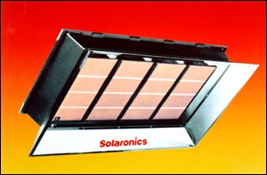
K - High Intensity Gas Infrared Heaters K-Series Gas Infra-Red Heaters HEATER
CERAMIC COMBUSTION SURFACE
MODELS & BTUH RATINGS
ACCESSORIES – Protective screens, secondary re-radiating wire grid, parabolic reflector extensions, heat shield available K-30 thru K-100 for decreased clearances to combustibles. K-SERIES SUGGESTED SHORT FORM SPECGas fired infra-red heaters shall be furnished and installed in accordance with local codes, building drawings and manufacturer's recommendations. Heaters shall be vented by positive air displacement of 4 CFM for natural or 5 CFM for propane gas and one square inch of net free inlet area shall be provided per 1,000 BTUH input. Heaters shall be capable of angle mounting from 0 degrees to 30 degrees*, without the use of an additional reflector. The ceramic radiant surface shall be horizontal when heater is installed at 0 degrees. Heaters shall be certified by the International Approval Services (IAS) for the American and the Canadian Gas Associations. Design certified to American National Standard Institute ANSI Z83.6 including compliance with section 2.9, Radiant Coefficient, without the use of a secondary re-radiating surface of either rods or screen. HEATER CONTROLS BURNER HEAD/COMBUSTION SURFACE The burner(s) shall include the ceramic combustion surface, a plenum chamber, a venturi mixer and shall be removable with a single screw for cleaning or replacement without disconnecting any gas, electrical or hanging device. The ceramic combustion surface shall be capable of reaching temperatures up to 1850 degrees F (an incandescent appearance) and withstand thermal shock when water quenched. It shall be a cordierite-based grooved ceramic of an exclusive permeable design whereby alternate rows of 230 perforations per square inch, terminate at the bottom of slots making one half of the flame below the top surface of the ceramic and creating a more intimate contact between flame and surface. This will increase the ceramic surface temperature and the radiant output while maintaining a lower gas input and achieving greater wind resistance. The Plenum chamber shall be of 20 ga. (.035") corrosion-free aluminized steel, one-piece fabrication and seamless no-weld construction. The plenum chamber shall utilize a one-piece stainless steel retainer to hold the ceramic surface in place around its entire perimeter, a 14 ga. (.083") aluminized steel, back bracket for holding it in place to achieve proper alignment of the surface, venturi and orifice. MAIN FRAME REFLECTORS Reflectors shall be of 21 ga. (0.032") Mirror Brite Aluminum Finish (highly polished). Reflector design (shape) shall be of standard design and be mounted to the heater at the factory. An optional certified parabolic reflector extension is used for concentrating infra-red energy, usually for spot heating or higher mounting height applications. Optional certified accessories: protective screens, secondary re-radiating wire grids, and heat shields available for K-30 thru K-100 for decreased clearances to combustibles above the heater. Heaters shall carry a manufacturer's limited warranty covering the combustion surface and burner components for a period of one (1) year. *Heaters of 70 to 100 MBTUH and 160 MBTUH shall be mounted 5 degrees to 30 degrees only. Solaronics, Inc. 704 Woodward Avenue Rochester, MI 48307 USA Toll Free: 800-223-5335 Phone: 248-651-5333 Fax: 248-651-0357 E-mail: sales@solaronicsusa.com Web site: http://www.solaronicsusa.com |