
FLUSH WALL CLEAR SPAN (FW)
Used where column-free floor area is required, with the additional
specification that columns must be contained within the girt space to allow
sidewalls to be finished in an unbroken, straight line. Less economical
than Rigid Frame Clear Span frames, which have no limitations on column
depth. Ideal for convenience stores, small office buildings and branch
banks.
FLUSH WALL CLEAR SPAN (FW)
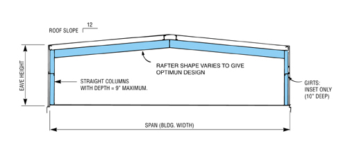
A Flush Wall Clear Span frame has a single ridge and consists of welded-up
rafter and column sections. Straight column sections are used with
depth limited to contain column entirely within the girt space. Columns
are pinned at base and continuous at top. Rafter is continuous throughout.
Frames are designed by computer analysis in accordance with accepted engineering
practices.
Clearances and Reactions
Due to the broad parameters available, it is impractical to give minimum
clearances and column reactions for the multiple combinations of width,
spans, eave height, roof slope, bay spacing, load and codes that are available.
However, for representative samples of the information that Ceco can furnish,
refer to the tables.
Clearances and reactions in the tables are given for frames with welded-up (solid web) rafter sections. They are not applicable to open web frames.
For actual frame clearances and reaction for any specific building,
and/or for open web frames, contact the nearest Ceco manufacturing facility.
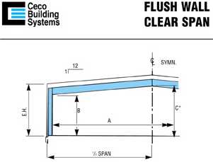
REPRESENTATIVE
CLEARANCE DIMENSIONS
1:12 ROOF SLOPE
BAY SPACING -- 25ft.
ROOF SLOPE -- 1:12
LIVE LOAD -- LL (psf)
WIND LOAD -- WL (mph)
WIND LOAD APPLIED IN ACCORDANCE WITH MBMA (1996)
*C = Minimum clearance other than at knee (dimension B). All points where rafter changes shape are checked and vertical dimension to lowest of these points is given.
**Clearances shown are approximate. Actual clearances may
be somewhat different.
Note: 1. Clearances shown are approximate. Actual
clearances may be somewhat different.
2.
Live loads greater than 30 pounds must be quoted. Please contact
the estimating department at your regional office.
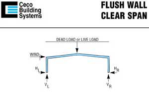
REPRESENTATIVE
FRAME REACTIONS
1:12 ROOF SLOPE
NOTES:
1. Dead load equals self weight of members.
2. Wind load is applied in accordance with MBMA (1996).
3. Negative value of reaction indicates direction opposite to that
shown on sketch.
4. Reactions shown are approximate only and are not exact submittal
values.
5. Reactions for various load combinations may be obtained by adding
or subtracting the appropriate values.
6. Forces on the foundation will act in the opposite direction to the
direction of the frame reactions.
Bay Spacing -- 25 ft.
Roof Slope -- 1:12
Live Load -- 20 psf
Wind Load -- 80mph
MODIFYING FACTORS:
To obtain approx. reactions for other bay sizes, live loads, and/or
wind loads use the following rules:
| BAY SIZE: (up to 30’) | Divide all reactions shown by 25 then multiply by the bay length required. | LIVE LOAD: | Divide live load reactions shown by 20 than multiply by the live load required. | |
| WIND LOAD: | Multiply the wind load
reactions shown by the applicable factor: 70 mph use 0.8 90 mph use 1.3 100-mph use 1.6 110-mph use 1.9 120 mph use 2.3 |