
Montel Inc.
The Intelligent Use of Space
225 4th Avenue, P.O. 130
Montmagny, QC G5V 3S5
Tel: (877) 935-0236
Fax: (418) 248-7266
E-mail: system@montel.com
Web site: http://www.montel.com
 Canada
Tel: (418) 248-0235
Toll-Free: (877) 935-0236
Fax: (418) 248-7266
system@montel.com
www.montel.com
USA
Tel: (321) 777-0464
Toll-Free: (877) 935-0236
Fax: (321) 777-3539
system@montel.com
www.montel.com
MOBILE STORAGE
1. PRODUCT PRESENTATION
A pioneer devoted to high-density mobile shelving storage system solutions,
Montel’s Mobilex® systems are dedicated
to the highest standards of quality for optimizing space utilization. Mobilex
high-density mobile shelving storage products are available for three type of
systems: manual, mechanical, and electrical.
Montel’s Mobilex systems offer several unique features:
- Smoothest operating system in the industry due to spherically designed double flanged load wheels which reduce friction;
- Large selection of safety and security devices;
- Aluminum sub-rail designed for use in a corrosive concrete environment;
- Designed to perform in a seismic zone;
- Electrical systems always operational even during power failures;
- Mobile and shelving systems are designed to make an intelligent use of space availability using the SmartTrack and the SmartShelf.
Montel’s engineers designed the Mobilex high-density mobile storage system with the following benefits in mind:
- Optimize space utilization;
- Maximize storage capacity;
- Reduce costs;
- Avoid renting or buying another building;
- Accommodate growth;
- Improve control, organization, productivity and workflow;
- Control unauthorized access.
Mobilex carriages systems can accommodate a variety of Montel shelving systems: SmartShelf (4-Post hybrid shelving), Cabinet Style (Case-type), Aetnastak (Cantilever library shelving), 4D Wide Span (4-Post long span shelving), extensive line of cabinets and a variety of new or existing shelving. The following is an overview of the Mobilex carriages characteristics:
| Electrical | Mechanical | Manual | |
| Power | Motor | Handle W/Gear Reduction | User directly |
| Technical Features | 5” diameter spherically designed double flanged wheels | 5” diameter spherically designed double flanged wheels | 5” diameter spherically designed double flanged wheels |
| Carriage Length | 3’ to 100’ | 3’ to 45’ | 3’ to 12’ |
| Carriage Width | 15” to 60” | 15” to 60” | 15” to 60” |
| Standard Load Capacity | 1000 lbs/linear ft | 1000 lbs/linear ft | 1000 lbs/linear ft |
The Mechanical Mobilex high-density mobile storage system offers the following design features:
- Full Length Drive Shaft on Every Carriage:
- Eliminates possible distortion;
- Reduces potential stress on the carriage structure;
- Enhances stability and performance;
- Provides positive tracking effect;
- Extends life of the systems.
- Two-Piece Rail:
- Provides better weight distribution at the junction;
- A two-piece rail embedded in a sub-rail is more reliable than a one-piece rail since it prevents both vertical and lateral movement;
- Low profile rail is flush with the finished floor.
- Riveted Carriage:
- Aircraft riveted technology usage allows consistency and precision;
- Assemblies using riveted carriages offers superior quality control;
- Rivets assembly provides easy and economical carriage modifications;
- Reduces material stress and increases the overall strength.
- 5” Diameter Spherically Designed Double-Flanged Steel Wheel:
- Spherical wheels reduce friction and increase smoothness of movement.
The Mechanical Mobilex high-density mobile storage system offer the following safety features:
- Locking mechanism.
The Electrical Mobilex high-density mobile storage system offers the following design features:
- Electrical Keypads:
- Safe and user-friendly buttons;
- Premium membrane allows unlimited operations;
- Membrane is more reliable than life-cycle mechanical push button keypads;
- Multiple languages.
- SmartTrack:
- Conceals the power wiring in the floor track offering more space and esthetically more appealing;
- Freedom to create aisles of various widths;
- U.S. Patent and Trademark Office approved product.
- Magnetic or Adjustable Infrared Proximity Sensor:
- Recessed and flush within the front end-panels;
- State-of-the-art reliability;
- Adjustable infrared proximity sensor;
- Aisles free of plungers or protruding parts;
- Maintenance free.
- Carriage Built-In Wire Raceway:
- Cables totally protected;
- Prevents cables from rubbing on floor or moving parts during operation;
- UL and Canadian Standards Association recommended.
- Control Board:
- Protected against radio frequency interferences and overloads;
- Easy installation plug-in type connectors;
- Diagnosis panel;
- Protected with fuses.
- Hinged Front Panels:
- Facilitates access to control boards Vs Boards mounted on top or under the carriages;
- Factory assembled.
- Motor:
- DC Motors on each carriage;
- Controlled Acceleration and deceleration;
- Each motor provides instant braking of mobile carriages.
- Auxiliary Power:
- Built-in Battery Back-up
- Always operational even during power outage
- Always recharging
- No hassle to find a battery pack in case of power failure
- Mechanical Ratchet
- Range moved with a ratchet tool
The Electrical Mobilex high-density mobile storage system offer the following safety features:
- Active Safeties:
- Floor-level and/or hip-level infrared safety sweep
- Emergency stop button and reset;
- Automatic lock/relock timer active safety;
- Controlled acceleration and deceleration.
- Passive Safeties:
- Human presence detector system;
- Entry sensor;
- Counting device;
- Overhead aisle lighting.
The Electrical Mobilex high-density mobile storage system offers the following security features:
- PIN code controlled access – HIPPA compliant;
- Mechanical and electro-mechanical locks for controlled access;
- Auto-park;
- Auto-spacing;
- Building interface;
- Magnetic card access reader.
Programmable options are available on the Electrical Mobilex high-density mobile storage system:
- Various languages;
- Main aisle access;
- Off-site monitoring;
- Preset features;
- Upgradable settings;
- Adjustable speed parameters;
- Auto-spacing;
- Computer interface;
- Programmable mobile/fixed carriage.
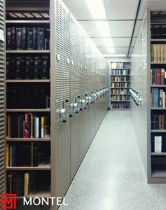
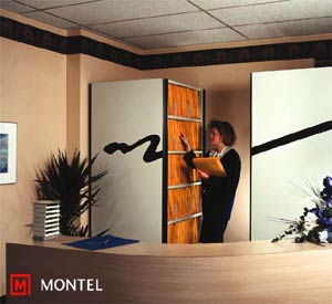
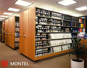
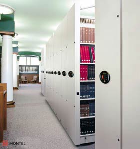
2. USES & APPLICATIONS
For efficient and space optimization storage needs, the Mobilex high-density
mobile storage system can be used in the following applications:
- Archives & Storage
- Business / Filing & Storage
- Educational & Libraries
- Government
- Healthcare
- Industrial
- Law & Justice
- Military
- Museums
- Retail / Residential
Recent Montel case studies documenting the use of Mobilex high-density mobile storage systems can be found on our Website at www.montel.com:
- Leading Public Library in Canada Uses Montel’s Shelving Systems, City of Vancouver, Vancouver, BC;
- Montel Provides Westminster Law Library with High-Density Mobile Shelving Solution, University of Denver, Denver, CO;
- Montel Provides Storage Solution to the U.S. Federal Aviation Administration, U.S. Federal Aviation Administration, Oklahoma City, OK;
- The Harold B. Lee Library Utilizes 98 Miles of Montel’s Cantilever Shelving, Brigham Young University, Provo, UT;
- Montel Solves Trinity University’s Space Problems, Trinity University, San Antonio, TX;
- Maricopa County Jail Relies on Montel’s High-Density Storage Systems, Maricopa County Criminal Justice Facilities, Phoenix, AZ;
- The National Archives of Canada Utilizes Montel Systems to Preserve the Documentary Heritage of Canada, National Archives of Canada, Gatineau, QC;
- Financial Institution's Client Accounts Doubled with Montel's Filing High-Density Solution, SouthSide Bank, Tyler, TX;
- A Publicly-Traded Homebuilder Uses Mobile to Improve Product Storage, Meritage Homes Corporation, Austin, TX;
- The National Baseball Hall of Fame and Museum Adopts Montel’s Storage Solutions, National Baseball Hall of Fame and Museum, Cooperstown, NY.
3. ASSEMBLY & INSTALLATION
Assembly and installation of Mobilex high-density mobile storage systems are
completed on site under the supervision of a factory trained Montel local authorized
dealer. Contact Montel or your local authorized dealer for details on assembly
and installation.
4. COMPONENTS & PARTS
The following picture identifies the principal components of Montel’s
Mobilex high-density mobile storage systems:

5. MATERIALS & FINISHES
Materials of the Mobilex high-density mobile storage system shall be the finest
of their respective kinds and those best adapted to the assembly for which they
are employed to meet ISO 9002 quality standards. All steel shall be the best
mild, cold rolled, pickled, and double annealed, free from scale and buckle.
All plating used on exposed parts shall be metallic furniture stock. All gauges
are U.S. standard. The design of all parts shall be such that the completed
installation shall present a neat and finished appearance and shall be free
from exposed sharp edges or projections.
All steel parts shall be smoothly made, and thoroughly cleaned by a process of washing completely in a phosphatizing solution to insure removal of oil, grease or other foreign material which in any way would interfere with the adhesion of the priming coat. Following the cleaning process, all parts shall be coated by spraying, assuring that every part in thoroughly and completely covered with fine baking enamel, or powder coat and baked to the manufacturer’s paint recommendation meeting ISO 9002 quality standards. The finish for baked enamel shall be medium gloss, giving a reading of 50 to 60 degrees on a standard gloss meter and must be capable of withstanding severe hammer and bending tests without flaking. Final finish shall be a minimum of 1.2 mil thickness capable of resisting acetic acid, household ammonia, 10% lye, alcohol, salt spray, abrasion and printing, and all normal usage resistant requirements of a good finish.
The finish for epoxy-polyester hybrid powder coat shall be a minimum 2.5 mil thickness capable of resisting the same test than the baked enamel coating described previously. Furthermore, powder coat shall not be off gassing to prevent deterioration of collection and other great value books.
For additional information on materials and finishes, see TECHNICAL SUPPORT
section.
6. TECHNICAL SUPPORT
6.1 MANUAL SYSTEM
Basis of Design: Products are based upon Manual Movable
Shelving Systems. Provide products complying with requirements of the following
specifications and made by Montel Inc.
Grout:
- General: The compound shall be a hydraulic type cement which, when mixed with water, will harden to produce a permanent bolt setting anchor. The compound shall conform to the following specifications, all of which are based on the performance of the test specimens at room temperature and in laboratory air.
- Linear Movement: It shall not shrink on setting, but shall exhibit a slight expansion of not more than .002 inch per linear inch.
- Compression Strength: Two inch cubes made in accordance with ASTM standards
tested on a Balding-Southward machine of 60,000 pounds capacity shall have
the following minimum average compression strengths:
Age: 1 hour - 4500 psi
7 days - 8000 psi - All tracks must be grouted the entire length of each run, including all rail joints. As the grout slightly expands during the cure process, it will be in permanent contact with the structural members being grouted. This will provide a continuous support to the system, and optimal weight distribution on the existing floor slab.
Track:
- Rails shall be designed and manufactured to carry loads of 1000 pounds per linear foot of carriage. Made of minimum cold rolled steel (CRS) rail assembly of 3/4” high x 1” wide is inserted in an aluminum sub rail treated against oxidation caused by concrete. Rail contact surface shall be minimum 1” wide. Anti-tip device is required to meet local building code.
- Rails shall be leveled with and not project above or below the walking surface.
- Rails shall be designed to be anchored on top of structural concrete floor and to allow for adjustment so rails can be leveled over an uneven floor.
- Maximum profile of recess adjacent to rail to accommodate manufacturer’s carriages guidance system and/or anti-tip system not exceeding 7/16” wide x 3/4” deep.
- All rail connection joints shall be designed to provide horizontal and vertical continuity between rail sections, to gradually transfer the concentrated wheel point load to and from adjoining sections.
- Rail shall be located and positioned properly, leveled and grouted, allowing at least 1/4” for grout under high point. Grout to be worked under rail, any voids completely filled and trimmed upsides and flush with rails. This will allow proper weight distribution from rail to existing slab.
- Levelness of rails: 3/32” maximum variation from true level within any module; 1/16” maximum variation between adjacent rails, perpendicular to rail direction; 1/32” maximum variation in 10”-0” of rail length, along any rail.
- Rails to be rechecked for integrity of position and levelness and anchored into structural concrete slab, using anchors in sizes and quantities as determined by manufacturer.
- Main rail section shall be a minimum of 10”-0” each with shorter sections used to terminate each individual rail assembly.
Floor Options:
- Floor/Ramp (Raised Floor)
- Finished elevation of the raised floor shall be flush with the top of the rails.
- The ramp shall not extend beyond the end of the carriages and shall have a maximum slope of nine degrees. The vertical transition from the ramp edge to the floor shall be a maximum of 1/8”. Ramps shall extend under all movable and stationary ranges except as noted differently. Ramps shall be made of 12-gauge steel.
- Floor panels shall be constructed of a minimum [5/8” or 3/4”] thick, underlayment grade plywood. Floor panels must be provided between all rails the full-width of modules, except under stationary platforms.
- The floor and ramp shall be constructed in a manner that will absolutely prevent any warping or deformation of the floor panels in a normal operating environment.
- Floor covering is to be installed and supplied by the Owner.
- Embedded Rails
- Finished elevation of the raised floor shall be flush with the top of the rails.
- Rail shall be protected with steel covers during the pouring process.
- Concrete topping shall be poured in order to fill the gap between existing slab and top of the rail (NIC).
Carriages:
- All carriages shall be riveted construction for flexibility. Welded carriages are unacceptable. Carriages and stationary platforms shall be constructed of minimum 12-gauge steel. 1000 pounds per linear foot minimum capacity.
- Fixed carriages, as shown on the drawings, shall be of same construction and height as the movable carriages and anchored to rails. Setting of shelving on floor at ends of mobile runs in unacceptable.
- Necessary carriage splices shall be bolted type designed to maintain proper unit alignment and weight load distribution.
- Carriage straightness shall have no more than 1/4” maximum deviation from a true straight line. There shall be no permanent set or slippage in any spiced or welded joint when exposed to forces encountered in normal operating circumstances.
- Carriage construction shall be so designed to allow the shelving uprights to be secured to the carriage frame with vibration proof anchor assemblies (2 per upright).
- Each carriage shall have two wheels per rail.
- Carriages shall be [powder coat] or [baked enamel finish] (1.5 mil) inside and out. Color selection by Owner to match shelving. [Powder coat] paint finish is required for finish durability and elimination of any off gassing. Finish has to be inert, with no volatiles present in finished product. Visible galvanized steel structural carriage components are unacceptable.
Drive System Design:
- Wheels are mounted on a 1” o.d. solid steel shaft. Manual system does not require gears.
Wheels:
- Wheels shall be constructed of solid minimum 1045 cold rolled steel (CRS) for smooth operation. Minimum load capacity per wheel 3540 pounds. Wheels shall be precision ground, balanced. All bearings shall be permanently shielded and lubricated.
- All wheels shall be minimum 5” diameter (outside dimension). They shall be double flanged and sloped to insure efficient guidance. Load wheels are spherical to reduce friction.
- Guide wheels shall be at all wheel locations.
Front Panels:
- All exposed face panels shall be steel (mandatory). Front panels shall be full-depth and height of shelving units. Panels to be located on all operating ends of ranges as shown on drawings.
Operation and Controls:
- Movement is achieved manually, with minimal effort, by means of pulling/pushing
a steel handle mounted on the end panel of each mobile range or directly on
the upright.
6.2 MECHANICAL SYSTEM
Basis of Design: Products are based upon Mechanical
Movable Shelving Systems. Provide products complying with requirements of the
following specifications and made by Montel Inc.
Grout:
- General: The compound shall be a hydraulic type cement which, when mixed with water, will harden to produce a permanent bolt setting anchor. The compound shall conform to the following specifications, all of which are based on the performance of the test specimens at room temperature and in laboratory air.
- Linear Movement: It shall not shrink on setting, but shall exhibit a slight expansion of not more than .002 inch per linear inch.
- Compression Strength: Two inch cubes made in accordance with ASTM standards
tested on a Balding-Southward machine of 60,000 pounds capacity shall have
the following minimum average compression strengths:
Age: 1 hour - 4500 psi
7 days - 8000 psi - All tracks must be grouted the entire length of each run, including all rail joints. As the grout slightly expands during the cure process, it will be in permanent contact with the structural members being grouted. This will provide a continuous support to the system, and optimal weight distribution on the existing floor slab.
Track:
- Rails shall be designed and manufactured to carry loads of 1000 pounds per linear foot of carriage. Made of minimum cold rolled steel (CRS) rail assembly of 3/4” high x 1” wide is inserted in an aluminum sub rail treated against oxidation caused by concrete. Rail contact surface shall be minimum 1” wide. Anti-tip device is required to meet local building code.
- Rails shall be leveled with and not project above or below the walking surface.
- Rails shall be designed to be anchored on top of structural concrete floor and to allow for adjustment so rails can be leveled over an uneven floor.
- Maximum profile of recess adjacent to rail to accommodate manufacturer’s carriages guidance system and/or anti-tip system not exceeding 7/16” wide x 3/4” deep.
- All rail connection joints shall be designed to provide horizontal and vertical continuity between rail sections, to gradually transfer the concentrated wheel point load to and from adjoining sections.
- Rail shall be located and positioned properly, leveled and grouted, allowing at least 1/4” for grout under high point. Grout to be worked under rail, any voids completely filled and trimmed upsides and flush with rails. This will allow proper weight distribution from rail to existing slab.
- Levelness of rails : 3/32” maximum variation from true level within any module; 1/16” maximum variation between adjacent rails, perpendicular to rail direction; 1/32” maximum variation in 10”-0” of rail length, along any rail.
- Rails to be rechecked for integrity of position and levelness and anchored into structural concrete slab, using anchors in sizes and quantities as determined by manufacturer.
- Main rail section shall be a minimum of 10”-0” each with shorter sections used to terminate each individual rail assembly.
Floor Options:
- Floor/Ramp (Raised Floor)
- Finished elevation of the raised floor shall be flush with the top of the rails.
- The ramp shall not extend beyond the end of the carriages and shall have a maximum slope of nine degrees. The vertical transition from the ramp edge to the floor shall be a maximum of 1/8”. Ramps shall extend under all movable and stationary ranges except as noted differently. Ramps shall be made of steel 12-gauge.
- Floor panels shall be constructed of a minimum [5/8” or 3/4”] thick, underlayment grade plywood. Floor panels must be provided between all rails the full width of modules, except under stationary platforms.
- The floor and ramp shall be constructed in a manner that will absolutely prevent any warping or deformation of the floor panels in a normal operating environment.
- Floor covering is to be installed and supplied by the Owner.
- Embedded Rails
- Finished elevation of the raised floor shall be flush with the top of the rails.
- Rail shall be protected with steel covers during the pouring process.
- Concrete topping shall be poured in order to fill the gap between existing slab and top of the rail (NIC).
Carriages:
- All carriages shall be riveted construction for flexibility. Welded carriages are unacceptable. Carriages and stationary platforms shall be constructed of minimum 12-gauge steel. 1000 pounds per linear foot minimum capacity.
- Fixed carriages, as shown on the drawings, shall be of same construction and height as the movable carriages and anchored to rails. Setting of shelving on floor at ends of mobile runs in unacceptable.
- Necessary carriage splices shall be bolted type designed to maintain proper unit alignment and weight load distribution.
- Carriage straightness shall have no more than 1/4” maximum deviation from a true straight line. There shall be no permanent set or slippage in any spiced or welded joint when exposed to forces encountered in normal operating circumstances.
- Carriage construction shall be so designed to allow the shelving uprights to be secured to the carriage frame with vibration proof anchor assemblies (2 per upright).
- Each carriage shall have two wheels per rail.
- Carriages shall be [powder coat] or [baked enamel finished] (1.5 mil) inside and out. Color selection by Owner to match shelving. [Powder coat] paint finish is required for finish durability and elimination of any off gassing. Finish has to be inert, with no volatiles present in finished product. Visible galvanized steel structural carriage components are unacceptable.
Drive/Guide System (Mandatory) Design:
- Provide drive shaft minimum 1-5/16” o.d. tubular steel or 1” o.d. solid steel, driving all wheels on one side of each carriage to provide even carriage movement, even under unbalanced load conditions.
Wheels:
- Wheels shall be constructed of solid minimum 1045 cold rolled steel (CRS) for smooth operation. Minimum load capacity per wheel 3540 pounds. Wheels shall be precision ground, balanced. All bearings shall be permanently shielded and lubricated.
- All wheels shall be minimum 5” diameter (outside dimension). They shall be double flanged and sloped to insure efficient guidance. Load wheels are spherical to reduce friction; drive wheels shall be flat.
- Guide wheels shall be at all wheel locations.
Front Panels:
- All exposed face panels shall be steel (mandatory). Front panels shall be full depth and height of shelving units. Panels to be located on all operating ends of ranges as shown on drawings.
Operation and Controls:
- The system shall be of the mechanical assist type having a chain sprocket drive system. A driving system is required to provide uniform movement along the total length of the carriage even with unbalanced loads on the carriage. The system shall be a positive drive to ensure that there is no play in the drive handle and that the carriage will stop without drifting. All components of the system shall be compatible for smooth non-jerking, even movement along the total length of the carriage. Drive system shall have a minimum gear ratio requiring 1 pound of pressure to move a load of 6000 pounds. All bearings used in the drive mechanism shall be permanently shielded and lubricated.
- Operating handles shall be three-spoke type with steel spokes (single spoke handles unacceptable), approximately 17” diameter, which transmit power through a chain drive to the drive wheels. Provide operating handles on drive end of carriages as noted on drawings. Each mechanical device shall come with a chain-tensioning.
Safety Options:
- Active safety (for single access): Shall consist of a locking pin located on the handle. The user has to push a knob which will then lock the respective carriage. Both carriages on each side of the aisle have to be secured.
- Active safety (for single or dual access): Shall consist of a lever arm which, once engaged after a 90-degree rotation, will lock the mechanism, preventing movement of the carriage. Carriages on both sides of the aisle has to be secured. In dual access application, a full-length shaft will connect both ends of carriage.
- Passive safety (for single or dual access): This system consists in a protecting
device which will be automatically activated, as soon as a more-than-three-inch
aisle is created, preventing the carriages from backing up (the user does
not have to activate the safety). Users will need to press the button and
simultaneously look in the opened aisle, before creating another aisle. In
dual access application, a steel wire will connect safety mechanisms at both
ends of carriages.
6.3 ELECTRICAL SYSTEM
Basis of Design: Products are based upon Electrical
Movable Shelving Systems. Provide products complying with requirements of the
following specifications and made by Montel Inc.
Grout:
- General: The compound shall be a hydraulic type cement which, when mixed with water, will harden to produce a permanent bolt setting anchor. The compound shall conform to the following specifications, all of which are based on the performance of the test specimens at room temperature and in laboratory air.
- Linear Movement: It shall not shrink on setting, but shall exhibit a slight expansion of not more than .002 inch per linear inch.
- Compression Strength: Two inch cubes made in accordance with ASTM standards
tested on a Balding-Southward machine of 60,000 pounds capacity shall have
the following minimum average compression strengths:
Age: 1 hour - 4500 psi
7 days - 8000 psi - All tracks must be grouted the entire length of each run, including all rail joints. As the grout slightly expands during the cure process, it will be in permanent contact with the structural members being grouted. This will provide a continuous support to the system, and optimal weight distribution on the existing floor slab.
Track:
- Rails shall be designed and manufactured to carry loads of 1000 pounds per linear foot of carriage. Made of minimum cold rolled steel (CRS) rail assembly of 3/4” high x 1” wide is inserted in an aluminum sub rail treated against oxidation caused by concrete. Rail contact surface shall be minimum 1” wide. Anti-tip device is required to meet local building code.
- Rails shall be leveled with and not project above or below the walking surface.
- Rails shall be designed to be anchored on top of structural concrete floor and to allow for adjustment so rails can be leveled over an uneven floor.
- Maximum profile of recess adjacent to rail to accommodate manufacturer’s carriages guidance system and/or anti-tip system not exceeding 7/16” wide x 3/4” deep.
- All rail connection joints shall be designed to provide horizontal and vertical continuity between rail sections, to gradually transfer the concentrated wheel point load to and from adjoining sections.
- Rail shall be located and positioned properly, leveled and grouted, allowing at least 1/4” for grout under high point. Grout to be worked under rail, any voids completely filled and trimmed upsides and flush with rails. This will allow proper weight distribution from rail to existing slab.
- Levelness of rails: 3/32” maximum variation from true level within any module; 1/16” maximum variation between adjacent rails, perpendicular to rail direction; 1/32” maximum variation in 10’-0” of rail length, along any rail.
- Rails to be rechecked for integrity of position and levelness and anchored into structural concrete slab, using anchors in sizes and quantities as determined by manufacturer.
- Main rail section shall be a minimum of 10’-0” each with shorter sections used to terminate each individual rail assembly.
Floor Options:
- Floor/Ramp (Raised Floor)
- Finished elevation of the raised floor shall be flush with the top of the rails.
- The ramp shall not extend beyond the end of the carriages and shall have a maximum slope of nine degrees. The vertical transition from the ramp edge to the floor shall be a maximum of 1/8”. Ramps shall extend under all moveable and stationary ranges except as noted differently. Ramps shall be made of steel 12-gauge.
- Floor panels shall be constructed of a minimum [5/8” or 3/4”] thick, underlayment grade plywood. Floor panels must be provided between all rails the full-width of modules, except under stationary platforms.
- The floor and ramp shall be constructed in a manner that will absolutely prevent any warping or deformation of the floor panels in a normal operating environment.
- Floor covering is to be installed and supplied by the Owner.
- Embedded Rails
- Finished elevation of the raised floor shall be flush with the top of the rails.
- Rail shall be protected with steel covers during the pouring process.
- Concrete topping shall be poured in order to fill the gap between existing slab and top of the rail (NIC).
Carriages:
- All carriages shall be riveted construction for flexibility. Welded carriages are unacceptable. Carriages and stationary platforms shall be constructed of minimum 12-gauge steel. 1000 pounds per linear foot minimum capacity.
- Fixed carriages, as shown on the drawings, shall be of same construction and height as the moveable carriages and anchored to rails. Setting of shelving on floor at ends of mobile runs in unacceptable.
- Necessary carriage splices shall be bolted type designed to maintain proper unit alignment and weight load distribution.
- Carriage straightness shall have no more than 1/4” maximum deviation from a true straight line. There shall be no permanent set or slippage in any spliced or welded joint when exposed to forces encountered in normal operating circumstances.
- Carriage construction shall be so designed to allow the shelving uprights to be secured to the carriage frame with vibration proof anch assemblies (2 per upright).
- Each carriage shall have two wheels per rail.
- Carriages shall be [powder coat] or [baked enamel finished] (1.5 mil) inside and out. Color selection by Owner to match shelving. [Powder coat] paint finish is required for finish durability and elimination of any off gassing. Finish has to be inert, with no volatiles present in finished product. Visible galvanized steel structural carriage components are unacceptable.
Wheels:
- Wheels shall be constructed of solid minimum 1045 cold rolled steel (CRS) for smooth operation. Minimum load capacity per wheel 3540 pounds. Wheels shall be precision ground, balanced. All bearings shall be permanently shielded and lubricated.
- All wheels shall be minimum 5” diameter (outside dimension). They shall be double flanged and sloped to insure efficient guidance. Load wheels are spherical to reduce friction; drive wheels shall be flat.
- Due to carriage length and shelving heights, guide wheels shall be at all wheel locations.
Front Panels:
- All exposed face panels shall be steel (mandatory). Front panels shall be full depth and height of shelving units. Panels to be located on all operating ends of ranges as shown on drawings.
Keypad Control Options:
- One Keypad per Module:
- Each module shall have one keypad control centered in the master panel and located 52” from the base. The keypad shall have a 32-character display, two arrow shaped OPEN buttons, a STOP button and a RESET button with a backlit red reset light. This master keypad will control the movement of all carriages in the module. The 32-character display will give the status of the system at any time.
- To operate the system, the user shall reach the master keypad, select the aisle to be open (aisles as to have to be numbered) and then press one of the two arrows. The master control shall have the capability to open any aisle within the module. Aisle shall open automatically regardless of the position of the carriages.
- Keypad on all Carriages (LCD Display on Master Control Only)
- Each carriage shall have one keypad control centered in the master panel and located 52” from the base. The master keypad shall have a 32-character display, two arrow shaped OPEN buttons, a STOP button and a RESET button with a backlit red reset light. The other keypads shall have two arrow shaped OPEN buttons, a STOP button and a RESET button with a backlit red reset light. The LCD master display keypad will give the status of the module at any time.
- To operate the system, the software offers two possibilities. First option, pressing the arrow pointing the selected aisle will open any moveable carriage in order to access the aisle selected. Second option, pressing the left or right arrow will determine the carriage movement in the chosen direction. Aisle shall then open automatically regardless of the position of the carriages.
- Keypad with LCD display on all carriages
- Each carriage shall have one keypad control centered in the master panel and located 52” from the base. All the keypads shall have a 32-character display, two arrow shaped OPEN buttons, a STOP button and a RESET button with a backlit red reset light. Each LCD display keypad will constantly give the status of the module and its related carriage.
- The software shall offer two programmable options to operate the system. As a first option, pressing the arrow pointing the selected aisle will initiate the proper carriage movement to access the aisle pointed by the arrow. As the second option, pressing the left or right arrow will initiate the proper carriage movement in the direction pointed by the arrow. In all cases, aisle shall open automatically regardless of the position of the carriages. Both options can be modified easily without requiring factory technician support.
Operations and Controls:
- Each carriage shall provide controlled acceleration and deceleration to protect stored books or objects. Each motor shall have a dynamic braking system which will stop the carriage whenever a safety feature is activated.
- Each module can be easily programmed or locked simply by pressing different button sequences on the master keypad, not requiring the utilization of special software.
- All controls and indicator lights shall be solid state and shall provide visual indication of safety system operation.
- System controls shall start motors sequentially to minimize power demand. Infrared proximity switches (mandatory) shall be adjustable. Mechanical plungers are not acceptable in order to minimize maintenance.
- Each carriage to be equipped with a minimum of one 90 VDC current limited, fractional horsepower gear-motor.
- Gear-motor shall be connected to a full-length shaft at all rail locations to avoid potential distortion.
- Controls shall provide sequential movement with a controlled running speed of 3” per second.
- System shall operate on 115 Volts 50/60 Hertz, 15 or 30 Amp dedicated circuit, depending on the quantity of carriages.
- Overhead scissor arms will distribute the power and provide communication between the carriages [SmartTrack concept avoiding scissor arms available - optional].
- Every potential aisle can be protected with an infrared toe-level safety beam, mounted on both sides of each moveable carriage, 3/4” from floor. Safety sweep using mechanical switches are not acceptable.
- Buttons with membrane technology are mandatory to ensure maximum life duration of controls. Mechanical push button keypads are not acceptable.
Optional Items:
- Human presence detectors shall be used to secure the opened aisle.
- Entry Sensor: Shall lock the system when a user enters an aisle. The next user will have to check the open aisle and press the reset before selecting a new aisle.
- Counting Device: Shall monitor users entering and exiting an aisle. The system will reset automatically once all users have left the aisle.
- Wire raceways shall be installed full-length within each carriage to protect the wires during the carriage movement.
- SmartTrack (does not require scissor arms): All the wiring carrying the data and the 120 V power between the carriages, shall be concealed in an aluminum extrusion (SmartTrack) located in the sub-floor underneath the carriages. The extrusion consists of two integrated raceways, located at the back of the system and running the full length of the module. Retractable cables carrying data shall be inserted in the smaller raceway and retractable cables carrying 120 V power shall be inserted in the larger raceway. Both cables are connected to a protective pipe anchored to the moveable carriages. Sealing strips shall close and protect the wires during the carriage movement.
- Hinged Front Panels: Designed to facilitate access to controls, made of 18 gauge steel, mounted on hinges, requiring a special tool to be opened.
- Auxiliary Power:
- Built-in Battery Back-Up Override: Electrical mobile system shall be always operational even during power failures. Battery must always be recharging. Requires one per module.
- Manual Ratchet: Carriage can be moved with a ratchet tool connected to the full-length shaft.
- Every potential aisle shall be protected with an infrared hip-level safety beam, mounted on the both sides of each moveable carriage.
- Overhead Aisle Lighting: Each aisle shall be equipped with automatic lighting. Can be interfaced with the counting device, entry sensor, motion detector or the building lighting system.
- PIN Code Controlled Access – HIPAA Compliant: The HIPAA compliant PIN code access shall provide security for confidential documents or materials. Different PIN codes can be allocated, allowing access to specific modules only.
- Electro-Mechanical Lock for Controlled Access: The whole system shall be closed and locked during designated time periods using an electro-mechanical lock (Note : This feature requires the PIN code controlled access option).
- Auto-Park: System shall be preprogrammed to close all ranges after a predetermined period of inactivity to protect stored material from sprinkler systems, light, dust, etc. This feature gives the option to close the system at specific times to prevent unauthorized access after work hours.
- Auto-Spacing: Once activated, aisle spacing shall be evenly distributed. The sequence shall be activated by an internal timer (preset time), a key switch located on the master panel or a dry contact from the customer building interface.
- Automatic Lock/Relock Timer Active Safety: Shall be programmed for a predetermined period to automatically lock or relock the system if inactive for more than the determined period. The next user will have to check the aisle and press the RESET button before selecting a new aisle.
- Building Interface: System shall be linked to the building interface (alarm, fire, police station, sprinkler system, power generator, lighting system).
- Magnetic Card Access Reader: Users can operate the system with a card swipe access.
- Various Languages: Digital keypad control safety messages shall be available in at least 3 languages: English, Spanish, French.
- Main Aisle Access: System shall be programmed so the most frequently used aisle is always opened by default after a predetermined period of inactivity.
- Off-Site Monitoring: System shall offer capability to diagnose, monitor and service installed systems from a distance via modem.
- Upgradable Settings: Control boards shall offer capability to be upgraded.
- Programmable Speed Parameters: Shall be accomplished by using the keypad.
- Programmable Mobile/Fixed Carriage: One or multiple moveable carriage(s) shall offer the possibility to be modified into one or multiple fixed carriage(s).
7. CODES & CERTIFICATIONS
Client satisfaction is an ongoing priority at Montel. In this respect, all our
employees are engaged in a continuous improvement process to provide a high-quality
product that fully meets the needs and expectations of our clients.
From the first contact to the completion of the project, we spare no effort to meet the requirements of our clients. Our network of local authorized dealers across the world are selected according to these same criteria, and based on their commitment to fulfill these standards.
Carriages, controls, wiring and wire raceways, and electrical hinged front panels are pre-assembled at the factory to facilitate and ensure quality of installation, thus exceeding UL and CSA regulations. Electrical systems are always thoroughly tested by industrial certified research centers and independent laboratories. Finally, Montel is ISO 9001 certified.
Subject to the conditions stated below, Montel warrants to the original purchaser and for the first installation that the equipment manufactured by it will be free from defects in materials and workmanship:
LIFETIME LIMITED WARRANTY: for the lifetime of the shelving structural frames.
10-YEAR LIMITED WARRANTY: for ten (10) years from the date of customer’s written acceptance of installation, for all carriage drive motors. During the 10-year warranty period, all parts are included at no cost for 10 years. Labor installation is included at no cost during the first year of the 10-year warranty period.
5-YEAR LIMITED WARRANTY: for five (5) years from the date of customer’s written acceptance of installation, for all equipment, other than structural frames and motors. During the 5-year warranty period, all parts are included at no cost for 5 years. Labor installation is included at no cost during the first year of the 5-year warranty period.
If, within each of the warranty period as indicated above, any equipment shall be proved to Montel's satisfaction to be so defective, such equipment shall be repaired or replaced at the option of Montel.
All warranty service for any equipment manufactured by Montel must be approved by an authorized Montel factory representative. This warranty shall not apply to equipment repaired by any party other than an authorized Montel representative or to defects or damage caused by acts of God or other circumstances beyond Montel's control, improper installation (unless installation was by authorized Montel installer), improper electrical supply or environmental conditions, improper operation, maintenance or storage, or other than normal use or service. This warranty shall be void if any portion of the purchase price shall be due but unpaid in accordance with the terms pursuant to which the equipment was sold.
EXCEPT FOR THE EXPRESS WARRANTIES SET FORTH ABOVE, MONTEL MAKES NO WARRANTIES, IMPLIED OR OTHERWISE, AND MONTEL SPECIFICALLY DISCLAIMS ANY IMPLIED WARRANTY OF MERCHANTABILITY OR FITNESS FOR A PARTICULAR PURPOSE.
LIMITATION OF LIABILITY: Repair or replacement of any defective equipment, or refund of the purchase price paid by the customer in the event Montel determines such equipment cannot be repaired or replaced, shall be the customer's exclusive remedy for breach of the warranty for product defects, however caused, and in no case shall Montel be liable for incidental, consequential, special or other damages, or loss of profits or revenues whether as a result of breach of contract or warranty, Montel's negligence, or otherwise. Montel shall have no liability for any advice or assistance rendered by any party outside the scope of Montel's written specifications for the manufacture, operation or maintenance of the warranted equipment.
8. ENVIRONMENTAL DATA
The mobile storage products are manufactured to meet and exceed environmental
standards and provide a long useful life. For its 100% fully recyclable product
components, Montel uses powder coat paint, which is durable and non-off gassing.
Montel uses low V.O.C. (Volatile Organic Compound) paints to reduce air pollution
thus releasing negligible and the lowest emissions of V.O.C. possible. The waste
from our coating operation is recyclable and collected for treatment according
to government and state regulations.
9. AVAILABILITY & COST
For all general or specific enquiries regarding the Mobilex high-density mobile
shelving storage product’s availability and cost, please contact directly
Montel or your local authorized dealer.
10. OPERATION & MAINTENANCE
Montel’s electrical Mobilex high-density mobile shelving storage product
has been designed for minimum maintenance:
- MOVING PARTS - All bearings and motor gearboxes are permanently lubricated and require no maintenance.
- RAILS - Rails must always be kept clean. Cleaning once a month is suggested.
- TOE-LEVEL SAFETY - Toe-level safeties are constantly self-verified for proper operation. Toe-level safeties consist of an infrared beam running along the full length of the carriage. Any toe-level safety malfunction must be immediately repaired.
- HUMAN PRESENCE DETECTOR (OPTION) – Human presence detectors are constantly verified for proper operation. Any malfunction must be immediately repaired.
- STOPPING DISTANCE - It is possible that the stopping distance between two ranges requires adjustment. This may be necessary due to different load conditions or larger goods stored. The stopping distance between two ranges can be individually adjusted. This can be done by varying the sensitivity of the infrared proximity detector used to locate the next range. The infrared detectors are located inside the control panel. The stopping distance can be increased by turning the sensitivity screw, located on the top of the infrared detector, clockwise.
- COUNTER (OPTION) - Counters inside the panels must be aligned so it locks the aisle each time somebody goes in the aisle. Red windows must be kept clean.
Montel’s mechanical Mobilex high-density mobile shelving storage product has been designed for minimum maintenance:
- TURNING PARTS - All bearings and sprockets are permanently lubricated and need no maintenance.
- Rails - Rails must be kept clean. Cleaning once a month is suggested.
Your system has been designed to withstand a maximum of 1000 pounds per linear foot of carriage. Overloading the system could result in damage and abnormal wearing of parts particularly to the wheels and bearings assembly. Please respect the system capacity.
For enquiries regarding the Mobilex high-density mobile shelving storage product’s
operation and maintenance, please contact directly Montel or your local authorized
dealer.