Perimeter Systems Designer Series Cornices
With 1-1/2" & 3" radius profiles, along with fascia covers, box trims & soffit trims, you can virtually design any type of cornice imaginable. From simple moldings, to complex multitiered cornices, our sculptured profiles will do the job. Features All aluminum cornice shapes are precision crafted in our plant using special built radius dies on a CNC Press – they are not roll formed which means they are uniform from end to end, piece to piece. Joint treatment consist of a concealed splice with a 3/8" expansion reveal. All cornice shapes and trims inter change with one another and are designed to be watertight, sealants are rarely necessary. Cornice Design #1
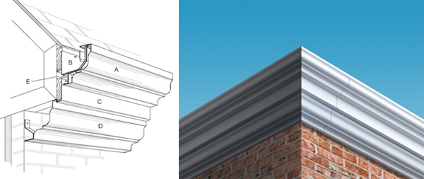
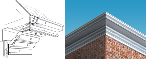
A. Designer Series DSR "Roman". Either the 6" or 8" profile may be used with this cornice design. If your project is subject snow and ice conditions, and your distance to the roof ridge is greater than 15' then you should lower the gutter below the roof's ice plane. You should also consider using snow guards. Simple adjustments to your framing will allow lowering the gutter system. B. Liner and bracket assembly. C. J-Cover with 3/8" expansion reveal joints. Installer should align joints with its mating upper Roman Gutter Fascia and Lower Roman Cornice Fascia. Installer should plan his cornice runs so that no section of the exposed components are shorter than 60". Joints that are equally spaced provides the most attractive assembly. D. Roman Cornice Trim with 3/8" expansion reveal joints. This trim is fastened to the roof truses and the fastener is covered by the J-Cover. The lower edge of the cornice is held in position with retaining brackets mounted to the wall at 30" centers. E. Venting the roof structure is possible by allowing an opening in your framing. The gutter fascia is held away from the J-Cover approximately 3/8" which allows venting. You should staple a hardware cloth over this opening as an insect screen. Cornice Design #2
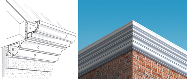
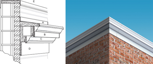
A. Designer Series DSC "Colonial". Either the 6" or 8" profile may be used with this cornice design. If your project is subject to snow and ice conditions, and your distance to the roof ridge is greater than 15' then you should lower the gutter below the roof's ice plane. You should also consider using snow guards. Simple adjustments to your framing will allow lowering the gutter system. B. Liner and bracket assembly. C. J-Cover with 3/8" expansion reveal joints. Installer should align joints with its mating upper Colonial Gutter Fascia and plan his cornice runs so that no section of the exposed components are shorter than 60". Joints that are equally spaced provides the most attractive assembly. The lower most J-Cover does not have a return leg and its joints should align with the LZ-1 trim. It is not necessary to align their joints with the Colonial Fascia & its' J-Cover joints. D. Soffit Panels (12" widths), v-groove, interlocking design. Panels can be solid, vented, or mixed to your preference. Front edge of panels are held in place with return edge of J-Cover and the interlock edge is nailed or screwed to the support framing. E. Cornice Trim Style "LZ-1 Type 6" with 3/8" expansion reveal joints. This trim is fastened to the support framing and its' fastener are covered by the Soffit Panels. The lower edge of the cornice is held in position with retaining brackets mounted at 30" centers. Cornice Design #3
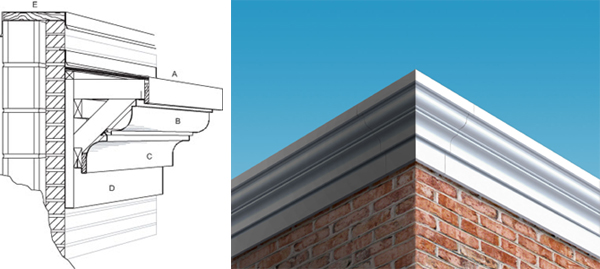
A. Designer Series DSR "Roman". Either the 6" or 8" profile may be used with this cornice design. If your project is subject to snow and ice conditions, and your distance to the roof ridge is greater than 15' then you should lower the gutter below the roof's ice plane. You should also consider using snow guards. Simple adjustments to your framing will allow lowering the gutter system. B. Liner and bracket assembly. C. Cornice 3" Concave Mould Type 4 with 3/8" expansion reveal joints. Installer should align joints with its mating upper Roman Gutter Fascia and Lower Cornice Fascia. Installer should plan his cornice runs so that no section of the exposed components are shorter than 60". Joints that are equally spaced provides the most attractive assembly. D. Cornice Convex Mould Type 3 with 3/8" expansion reveal joints. Installer should align joints with its mating upper Cornice Fascia. Installer should plan his cornice runs so that no section of the exposed components are shorter than 60". Joints that are equally spaced provides the most attractive assembly. E. Cornice Mounting Bracket fastened at each truss. Cornice Design #4
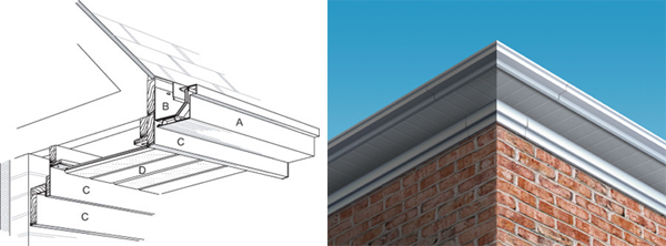
B. Liner and bracket assembly. C. J-Cover with 3/8" expansion reveal joints. Installer should align joints for both upper and lower J-Covers. Installer should plan his cornice runs so that no section of the exposed components are shorter than 60". Joints that are equally spaced provides the most attractive assembly. Note that J-Covers can be ordered for any type dimensional lumber. D. Soffit Panels (12" widths), v-groove, interlocking design. Panels can be solid, vented, or mixed to your preference. Front edge of panels are held in place with return edge of J-Cover and the interlock edge is nailed or screwed to the support framing. Cornice Design #5:
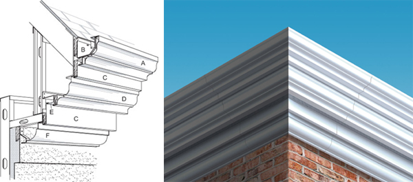
B. Liner and bracket assembly. C. J-Cover with 3/8" expansion reveal joints. Installer should align joints for all cornice trims. Installer should plan his cornice runs so that no section of the exposed components are shorter than 60". Joints that are equally spaced provides the most attractive assembly. Note that J-Covers can be ordered for any type dimensional lumber. D. Roman Gable Trim with 3/8" expansion reveal joints E. Recessed Continuous Soffit Vent F. 3" Convex Mould Type 6 (modified) with 3/8" expansion reveal joints. Cornice Design #6
B. Liner and bracket assembly. C. 3" Concave Mould (Type 5 @ gutter, Type 4 @ soffit) with 3/8" expansion reveal joints. Installer should align joints for all cornice trims. Installer should plan his cornice runs so that no section of the exposed components are shorter than 60". Joints that are equally spaced provides the most attractive assembly. C-1. 3" Concave Mould Type 1 with 3/8" expansion reveal joints. D. Soffit Panels (12" widths), v-grove, interlocking design. Panels can be solid, vented, or mixed to your preference. These soffit panel lengths are cut to accomodate the eave's overhang dimension. E. Box Trim with 3/8" expansion reveal joints. Installer should align joints for all cornice trims. Installer should plan his cornice runs so that no section of the exposed components are shorter than 60". Joints that are equally spaced provide the most attractive assembly. Cornice Design #7
B. Liner and bracket assembly. C. Box Trim with 3/8" expansion reveal joints. Installer should align joints for all cornice trims. Installer should plan his cornice runs so that no section of the exposed components are shorter than 60". Joints that are equally spaced provides the most attractive assembly. Note that Box Trims can be ordered for any type dimensional lumber. D. Soffit Panels (12" widths), v-groove, interlocking design. Panels can be solid, vented, or mixed to your preference. Front edge of panels are held in place with return edge of J-Cover and the interlock edge is nailed or screwed to the support framing. E. 3" Convex Mould Type 4 (modified) with 3/8" expansion reveal joints. Installer should align joints for all cornice trims. Installer should plan his cornice runs so that no section of the exposed components are shorter than 60". Joints that are equally spaced provides the most attractive assembly. E-1. 3" Convex Mould Type 3 with 3/8" expansion reveal joints. Cornice Design #8
B. Custom LZ Top Cornice Trim with 3/8" expansion reveal joints. Installer should align joints for all cornice trims. Installer should plan his cornice runs so that no section of the exposed components are shorter than 60". Joints that are equally spaced provides the most attractive assembly. C. Custom LZ Bottom Cornice Trim with 3/8" expansion reveal joints. Installer should align joints for all cornice trims. D. Freeze Board Trim with 3/8" expansion reveal joints. Installer should align Freeze Board joints with all other cornice trims. Freeze boards can be ordered to fit plywood or dimensional lumber. E. Coping Cap, see our Industrial Series Design Manual for coping options. Cornice Design #9
B. 3" Convex Mould Type 4 (modified) with 3/8" expansion reveal joints. Installer should align joints for all cornice trims. Installer should plan his cornice runs so that no section of the exposed components are shorter than 60". Joints that are equally spaced provides the most attractive assembly. C. 3" Concave Mould Type 2 with 3/8" expansion reveal joints. Installer should align joints for all cornice trims. D. Freeze Board T rim with 3/8" expansion reveal joints. Installer should align Freeze Board joints with all other cornice trims. Freeze boards can be ordered to fit plywood or dimensional lumber. E. Coping Cap, see our Industrial Series Design Manual for coping options. Cornice Design #10
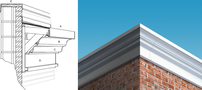
B. 3" Concave Mould Type 4 (modified) with 3/8" expansion reveal joints. Installer should align joints for all cornice trims. Installer should plan his cornice runs so that no section of the exposed components are shorter than 60". Joints that are equally spaced provides the most attractive assembly. C. LZ 1 Type 3 Cornice Trim with 3/8" expansion reveal joints. Installer should align joints for all cornice trims. D. Freeze Board Trim with 3/8" expansion reveal joints. Installer should align Freeze Board joints with all other cornice trims. Freeze boards can be ordered to fit plywood or dimensional lumber. E. Coping Cap, see our Industrial Series Design Manual for coping options. |

